
Mechanical vibration damping device for height-limited positioning

A vibration damping device and mechanical technology, applied in the direction of transportation and packaging, substructure, vehicle parts, etc., can solve problems such as uneven transportation and damage to transported goods, and achieve the effect of reducing vibration and enhancing practical value

Active Publication Date: 2016-11-30
JIANGSU HAIPENG SPECIAL VEHICLES +1
View PDF4 Cites 0 Cited by
  • Summary
  • Abstract
  • Description
  • Claims
  • Application Information

AI Technical Summary

Problems solved by technology

[0002] At present, when the middle frame and the rear frame, the middle frame and the front frame of most special transport vehicles in China are connected by hinged shafts, during the driving of the vehicle, due to emergency braking, there will be a gap between the two connected frames. Nodding phenomenon, resulting in unstable transportation, which in turn leads to damage to the transported goods

Method used


Image

  • Mechanical vibration damping device for height-limited positioning
  • Mechanical vibration damping device for height-limited positioning
  • Mechanical vibration damping device for height-limited positioning

Examples


Embodiment Construction

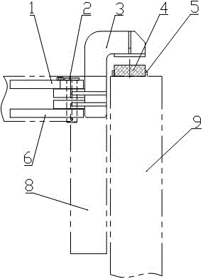
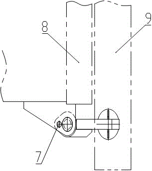
[0029] see figure 1 — figure 2 , the present invention relates to a mechanical damping device for height-limited positioning, which is composed of a rotating platen assembly welding 3, a base hole plate, a pin shaft 2, a circular nylon plate 4, and a nylon plate limit ring 5, the base The orifice plate is divided into an upper base orifice plate 1 and a lower base orifice plate 6. There is a gap between the upper base orifice plate 1 and the lower base orifice 6, and they are welded on the rear frame 8 respectively. The welding 3 is placed in the gap between the upper base orifice 1 and the lower base orifice 6, and is connected with the base orifice through the pin 2, and the nylon plate spacer ring 5 is placed on the top of the middle frame 9 and The corresponding position when the rotating pressure plate welding 3 plays the role of height limit positioning, and welded on the middle frame 9, the circular nylon plate 4 is placed inside the nylon plate limit ring 5, and glue...


PUM


Abstract

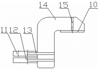
The invention relates to a mechanical shock absorption device for height limiting location. The mechanical shock absorption device is formed by a rotary pressing plate assembling and welding device (3), a base hole plate, a pin shaft (2), a circular nylon plate (4) and a nylon limiting ring (5), wherein the main structure, namely the rotary pressing plate assembling and welding device (3), is formed by a circular plate (10), an upper hole plate (11), a lower hole plate (12), a rib plate I (13), a pressing plate (14) and a rib plate II (15). The circular plate (10), the upper hole plate (11), the lower hole plate (12), the rib plate I (13), the pressing plate (14) and the rib plate II (15) are all in a welding connection mode. According to the mechanical shock absorption device for the height limiting location, disclosed by the invention, whether a height limiting location shock absorption function needs to be started or not can be selected by assembling and disassembling a locating pin (7), the relation between a middle vehicle frame (9) and a rear vehicle frame (8) is not affected when the height limiting location shock absorption function is not started, a height limiting location function is achieved when the function is started through rotation, and the vibration on a vehicle frame due to emergency brake during a driving process can be reduced.

Description

technical field [0001] The invention relates to a mechanical damping device for height-limited positioning, which can be used to connect the middle frame and the rear frame or the middle frame and the front frame to play the role of height-limited positioning and reduce During the process, the vibration caused by the emergency braking to the frame prevents the phenomenon of nodding between the connected frames during emergency braking. It belongs to the field of special auxiliary equipment. Background technique [0002] At present, when the middle frame and the rear frame, the middle frame and the front frame of most special transport vehicles in China are connected by hinged shafts, during the driving of the vehicle, due to emergency braking, there will be a gap between the two connected frames. The nodding phenomenon causes the transportation to be unstable, which in turn leads to the damage of the transported goods. Contents of the invention [0003] The object of the...

Claims


Application Information

Patent Timeline
Patent Type & Authority Patents(China)
IPC IPC(8): B62D21/00
CPCB62D21/18
Inventor 张利元康绍鹏赵静一周生保周爱斌陈艳品解安生
Owner JIANGSU HAIPENG SPECIAL VEHICLES
Learn More