
Cable arrangement, discharging and clamping device

A clamping device and wire-arranging technology, applied in the directions of packaging and bundling machinery parts, etc., can solve the problems of troublesome operation, disorder, winding and bundling, etc., and achieve the effect of simple structure and convenient use.

Inactive Publication Date: 2015-03-11
RONGCHENG ZHONGYUAN ELECTRIC APPLIANCE
View PDF5 Cites 3 Cited by
  • Summary
  • Abstract
  • Description
  • Claims
  • Application Information

AI Technical Summary

Problems solved by technology

Since the existing cable distribution tools do not have the clamp function, the free cable is out of the control of the human hand after it enters the U-shaped tiger's mouth, and sometimes it will be scattered, showing a messy state, which is not conducive to the winding and binding of the subsequent actions.
In this way, it is necessary to adjust the size of the U-shaped tiger mouth of the wiring tool to meet the requirements of the uniformity of the wiring, and the operation is quite troublesome.

Method used


Image

  • Cable arrangement, discharging and clamping device
  • Cable arrangement, discharging and clamping device
  • Cable arrangement, discharging and clamping device

Examples


Embodiment Construction

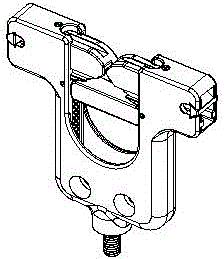
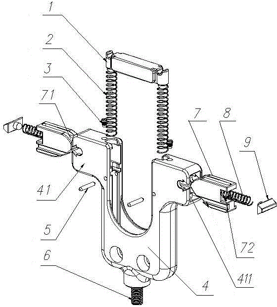
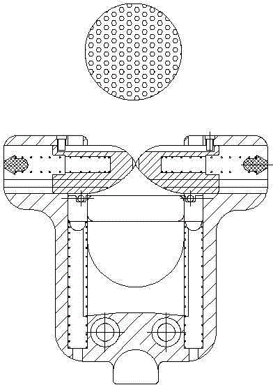
[0018] from figure 1 , figure 2 It can be seen from the figure that a clamping device for arranging and arranging cables includes a U-shaped clamping body 4, and the lower part of the clamping body is provided with a connecting stud 6 for mounting on a workbench. The U-shaped clamping body 4 A push plate 1 that can move up and down is installed horizontally in the two columns, and a spring 2 is installed in the column, and the push plate 1 is supported and floated by the spring 2 in the column; the upper parts of the two columns are symmetrically provided with baffle supports extending outward Arm 41, the baffle plate 7 that can move horizontally in and out is installed in the baffle support arm 41, and the baffle plate 7 is controlled to move by the baffle spring 8 installed in the baffle support arm, and the outer end of the baffle spring 8 is provided with a spring Briquetting 9.

[0019] Further, one end of the inner side of the two baffles 7 is provided with a smooth t...


PUM


Abstract

The invention relates to a cable arrangement, discharging and clamping device, which comprises a U-shaped clamping body, wherein the lower part of the clamping body is provided with a connecting stud, the connecting stud is arranged on a worktable, a vertical moving type push plate is horizontally arranged between two vertical columns of the U-shaped clamping body, a spring is arranged in each vertical column, the push plate is supported and floated by the springs in the vertical columns, the upper parts of the vertical columns symmetrically outwards extend to form retaining plate support arms, a retaining plate is arranged in each retaining plate support arm, is horizontally moved from interior to exterior or from exterior to interior, and is controlled by a retaining plate spring to move, each retaining plate spring is arranged in the corresponding retaining plate support arm, a spring pressure block is arranged at the outer end of each retaining plate spring, smooth transition surfaces are respectively arranged at the upper part and the lower end of one end of the inner sides of the two retaining plates, and the inner sides of the two retaining plates can be mutually touched and closed under the action of the retaining plate springs. The cable arrangement, discharging and clamping device has the advantages that the structure is simple and reasonable, the convenience in operation and use is realized, and the cable arrangement and discharging and automatic clamping are realized; after the cable is wound and bundled, only the cable needs to be lifted upwards.

Description

technical field [0001] The invention relates to the technical field of wire rods, in particular to a wire arranging and arranging clamping device. Background technique [0002] In order to arrange the complicated cables in an orderly manner, the cables are usually arranged together using a cable distribution tool, and then manually wound and bundled. Existing cable distribution tools generally include a U-shaped clamping body, and two transverse baffles are symmetrically arranged on the tiger's mouth of the U-shaped clamping body. During operation, manually press the arranged free cable, the free cable enters the U-shaped tiger mouth under the two horizontal baffles, the horizontal baffle is reset, and the free cable is blocked in the U-shaped tiger mouth. Then the operator frees up his hands for the next step of winding and bundling. Since the existing cable distribution tool does not have a clamp function, the free cable is out of manual control after entering the U-shap...

Claims


Application Information

Patent Timeline
Patent Type & Authority Applications(China)
IPC IPC(8): B65B67/00B65B13/18
CPCB65B67/00B65B13/18
Inventor 钱金玉金应基
Owner RONGCHENG ZHONGYUAN ELECTRIC APPLIANCE
Learn More