Composite movement mechanism

A compound motion, consistent technology, applied in mechanical equipment, transmission, belt/chain/gear and other directions, can solve the problems of difficult to achieve a variety of motion states, difficult to change, complex structure, etc., to achieve simple structure and diverse motion states. , control simple effects

Inactive Publication Date: 2015-03-11
常州天健管理咨询有限公司
View PDF0 Cites 5 Cited by
  • Summary
  • Abstract
  • Description
  • Claims
  • Application Information

AI Technical Summary

Problems solved by technology

[0002] The current control motion mechanism is various, but most of the control motion mechanisms can only control one kind of motion, and it is impossible or difficult to realize the control of multiple motion states. The structure of the existing compound motion control mechanism is complex, resulting in high cost. , and it is not easy to adjust the change of its control motion state, and there are great limitations

Method used


Image

  • Composite movement mechanism

Examples


Embodiment 1

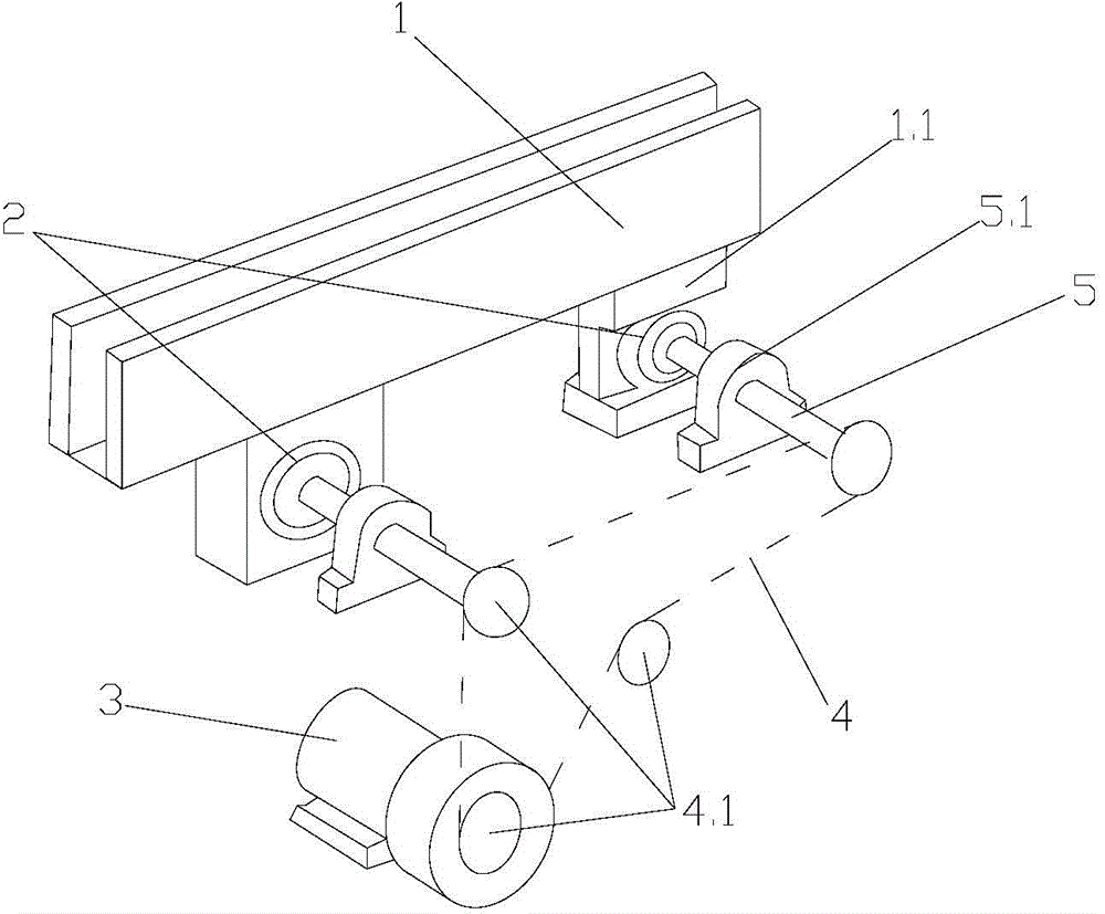
[0011] Example 1: Reference figure 1 , A compound motion mechanism, including straight slot type hopper 1, cam 2, motor 3, and transmission assembly. The number of cams 2 is two, which are correspondingly arranged at the bottom ends of hopper 1. The transmission assembly includes chain 4 and several sprockets. 4.1. The drive shaft 5 connected with the sprocket 4.1. One end of the drive shaft 5 is connected with the sprocket 4.1, and the other end extends to the bottom of the hopper 1 to connect with a fixed cam 2. The bottom of the hopper 1 is provided with a cam seat 1.1 that matches with the cam 2. The cam seat 1.1 There is a cam cavity, the cam 2 is set in the cam cavity, the drive shaft 5 is supported and fixed by the fixing base 5.1, the motor 3 is set at the bottom of the hopper 1, the output shaft of the motor 3 is provided with a sprocket 4.1, and the chain 4 is connected to the sprocket 4.1 for transmission , The eccentricity of the two cams 2 is the same, so that both...

Embodiment 2

[0012] Example 2: Reference figure 1 , A compound motion mechanism, including straight slot type hopper 1, cam 2, motor 3, and transmission assembly. The number of cams 2 is two, which are correspondingly arranged at the bottom ends of hopper 1. The transmission assembly includes chain 4 and several sprockets. 4.1. The drive shaft 5 connected with the sprocket 4.1. One end of the drive shaft 5 is connected with the sprocket 4.1, and the other end extends to the bottom of the hopper 1 to connect with a fixed cam 2. The bottom of the hopper 1 is provided with a cam seat 1.1 that matches with the cam 2. The cam seat 1.1 There is a cam cavity, the cam 2 is set in the cam cavity, the drive shaft 5 is supported and fixed by the fixing base 5.1, the motor 3 is set at the bottom of the hopper 1, the output shaft of the motor 3 is provided with a sprocket 4.1, and the chain 4 is connected to the sprocket 4.1 for transmission , The eccentricity of the two cams 2 is inconsistent, causing ...


PUM


Abstract

The invention relates to the technical field of movement mechanisms and particularly relates to a composite movement mechanism which comprises a hopper, cams, a motor and a transmission assembly, wherein the hopper is a straight slot type hopper; the at least two cams are uniformly arranged at the bottom end of the hopper; the transmission assembly comprises a chain, a plurality of chain wheels and a transmission shaft connected with the chain wheels, wherein one end of the transmission shaft is connected to the chain wheels, the other end of the transmission shaft extends to a position below the hopper and is connected and fixed with the cam; a cam base is arranged on the bottom of the hopper, a cam cavity is formed in the cam base, the cams are arranged in the cam cavity; the transmission shaft is supported and fixed by virtue of a fixing base; the motor is arranged on the bottom of the hopper; the chain wheels are arranged on the output shaft of the motor, and the chains are connected with the chain wheels for transmission. The eccentric directions of the cams are consistent or inconsistent. The composite movement mechanism is simple in structure, various in movement state, convenient to control and regulate, low in cost and high in efficiency.

Description

Technical field [0001] The invention relates to the technical field of motion mechanisms, in particular to a composite motion mechanism. Background technique [0002] There are various control motion mechanisms at present, but most of the motion control mechanisms can only control one motion correspondingly, and it is impossible or difficult to control multiple motion states. The structure of the existing compound motion control mechanism is complicated, which leads to high costs. , And the adjustment of its control motion state is not easy to achieve, and there are great limitations. Summary of the invention [0003] The technical problem to be solved by the present invention is to provide a compound motion mechanism with simple structure, diverse motion states, convenient control and adjustment, low cost and high efficiency in view of the above-mentioned defects. [0004] The technical solutions adopted by the present invention to solve its technical problems are as follows: [00...

Claims


Application Information

Patent Timeline
Patent Type & Authority Applications(China)
IPC IPC(8): F16H37/12
CPCF16H37/12
Inventor 庞小刚
Owner 常州天健管理咨询有限公司
Why Eureka
Try Eureka