Orthopedic kirschner pin bending device

A Kirschner wire and bender technology, applied in the field of orthopedic Kirschner wire benders, can solve the time-consuming and labor-intensive problems of needle holders or forceps

A Kirschner wire and bender technology, applied in the field of orthopedic Kirschner wire benders, can solve the time-consuming and labor-intensive problems of needle holders or forceps

CN104414727AInactive Publication Date: 2015-03-18ZHENGZHOU ZEZHENG TECHN SERVICES

Image

  • Orthopedic kirschner pin bending device
  • Orthopedic kirschner pin bending device
  • Orthopedic kirschner pin bending device

Examples


Embodiment Construction

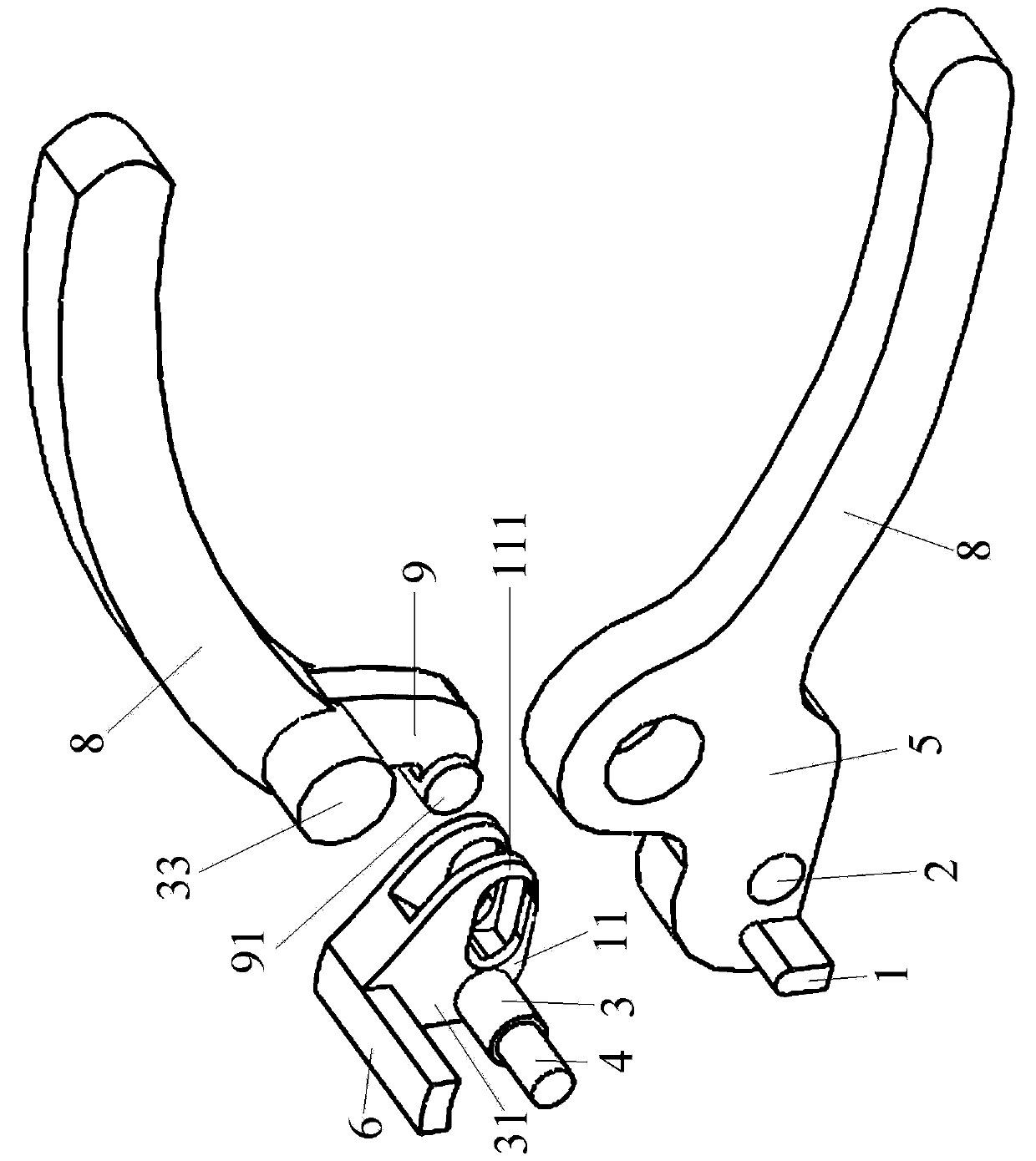
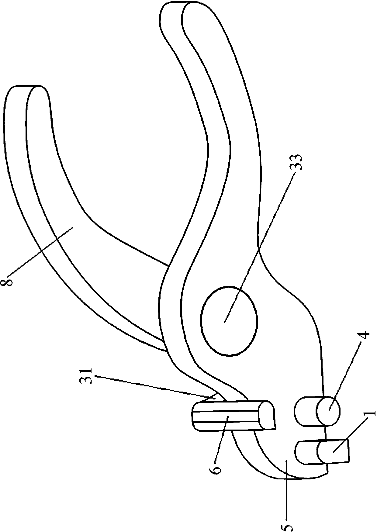
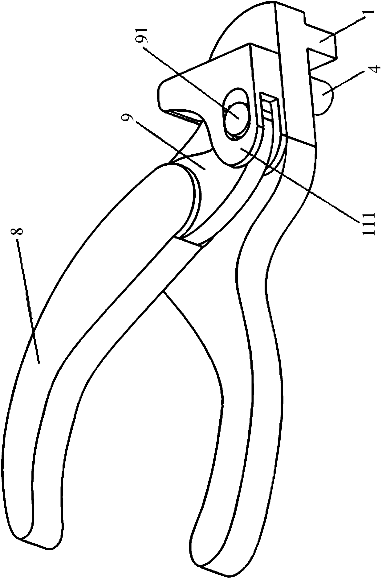
[0049] like figure 1 , figure 2 and image 3 As shown, the forming core block 1 is fixed on the base 5, the base 5 is provided with a shaft hole 2, and the shaft hole 2 is provided with a rotating shaft 3, and the rotating shaft 3 protrudes from the shaft hole to form a limiting column 4, and the limiting column 4 and the forming core block 1 jointly locates the Kirschner wire 19, and the rotating shaft 3 fixes the shifting block 6 through the connecting piece 31. In this way, the forming core block 1 and the limiting column 4 limit the Kirschner wire 19, so that the rotating shaft 3 rotates, and the shifting block 6 moves the g The needle 19 is bent around the forming core block 1 to form a hook-shaped elbow. In order to make the shifting block 6 not slip off in the process of moving the Kirschner wire 19, an arc-shaped groove 61 can be set on the shifting block 6 at the position in contact with the Kirschner wire 19, and the setting position of the arc-shaped groove 61 is...


PUM


Abstract

The invention discloses an orthopedic kirschner pin bending device. A formed core block is fixed on a base which is provided with a shaft hole; a rotating shaft is arranged in the shaft hole; the rotating shaft extends out of the shaft hole to form a limiting column; a kirschner pin is positioned through the limiting column and the formed core block together; a shifting block is fixed through a connecting part due to the rotating shaft. According to the orthopedic kirschner pin bending device, the kirschner pin is often clamped through a tong head first in the prior art and is forcibly to be bent under the clamped state, the time and the labor are consumed, and the shifting block which rotates around the rotating shaft shifts the kirschner pin to be bent around the formed core block to form a standard hooked elbow.

Description

technical field [0001] The invention relates to a surgical medical instrument, in particular to an orthopedic Kirschner wire bender. Background technique [0002] In orthopedic surgery, Kirschner wires are often used as steel needles for docking and fixing broken bones. Generally, Kirschner wires are about 20 centimeters in diameter, and there are several different specifications between 0.5 and 3 millimeters in diameter. It is used to fix small fractures or avulsion fractures and other fractures with low stress. It is also often used in the fixation of temporary fracture blocks in orthopedic surgery. During the operation, the Kirschner wires can be cut according to the size of the docking bone, and then inserted into the drilled bone for fixation, and the steel needles exposed outside the bone can be bent to prevent them from being left behind. The needle tail on the surface of the bone sticks out of the skin or sinks into the surface of the bone and cannot be removed late...

Claims


Application Information

Patent Timeline
18 Mar 2015
Publication
CN104414727A
IPC
A61B17/88
CPC
A61B17/8863
Inventors
ηŽ‹ζ™“; 肖艳