
Extractor hood and oil cup thereof

A range hood and oil cup technology applied in the field of kitchen appliances

Active Publication Date: 2015-03-18
BSH ELECTRICAL APPLIANCES JIANGSU
View PDF5 Cites 6 Cited by
  • Summary
  • Abstract
  • Description
  • Claims
  • Application Information

AI Technical Summary

Problems solved by technology

The present invention is provided with the anti-leakage part between the side wall and the first fixing part, so that the waste oil dripping on the first fixing part will not directly overflow from the top of the side wall, but flow into the lower part of the oil-leakage preventing part. The concave space is finally introduced into the inside of the oil cup, thus solving the oil leakage problem of the existing oil cup

Method used


Image

  • Extractor hood and oil cup thereof
  • Extractor hood and oil cup thereof
  • Extractor hood and oil cup thereof

Examples


Embodiment Construction

[0028] In order to have a further understanding of the purpose, structure, features, and functions of the present invention, the following detailed descriptions are provided in conjunction with the embodiments.

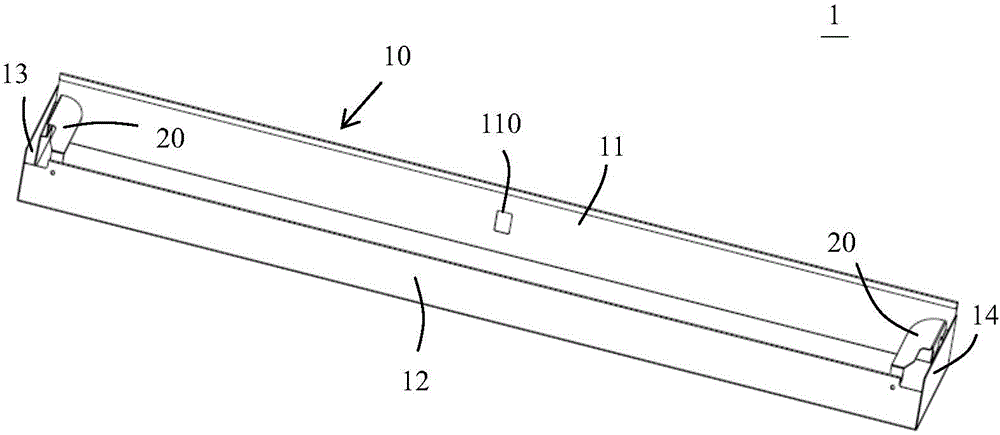
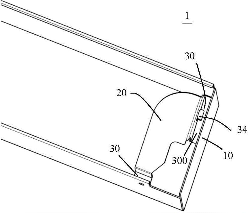
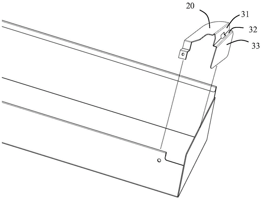
[0029] Such as figure 1 As shown, figure 1 It is a perspective view of an oil cup for a range hood according to an embodiment of the present invention. The oil cup 1 for a range hood of the present invention has an open top. The oil cup 1 includes an open side wall 10 and a first located inside the side wall 10 for fixing the oil cup 1 on the range hood. Fixing pieces 20. Please refer to figure 2 , figure 2 It is a perspective view of an oil cup according to an embodiment of the present invention. The oil cup 1 further includes an oil leakage prevention part connected between the side wall 10 and the first fixing member 20, and the oil leakage prevention part has a side adjacent to the side wall 10 and A recessed space 300 lower than the top end of the side wall 10. ...


PUM


Abstract

The invention provides an extractor hood and an oil cup thereof, wherein the top of the oil cup is provided with an opening, the oil cup comprises a side wall enclosing the opening and a first fixing member positioned in the side wall and used for fixing the oil cup on the extractor hood. The oil cup further comprises an oil leakage preventing part, wherein the oil leakage preventing part is connected between the side wall and the first fixing member, and provided with a concave space which is adjacent to the side wall and lower than the top end of the side wall. According to the oil cup, the oil leakage preventing part is arranged between the side wall and the first fixing member, therefore, waste oil dropping in the first fixing member can not directly overflow from the top end of the side wall and can flow in the concave space of the oil leakage preventing part, and finally is guided inside the oil cup, so that the problem of oil leakage of an existing oil cup is solved.

Description

【Technical Field】 [0001] The invention relates to the field of kitchen home appliances, in particular to an oil cup for a range hood and a range hood with the oil cup. 【Background technique】 [0002] Existing range hoods, especially side-suction range hoods, generally use a long box-shaped open oil cup, and the way of snapping or inserting is more convenient for the installation and disassembly of this type of oil cup. Therefore, the top of the side wall of the oil cup is often provided with a horizontal fold turned inward to facilitate the installation of the oil cup. However, the waste oil dripping on the horizontal flange often flows out of the oil cup along the side wall, and eventually causes oil leakage, which brings troubles to users in using and cleaning the range hood. [0003] Unless there is sufficient evidence to support it, the prior art described here does not mean that these prior art are known to those of ordinary skill in the field involved in the present applicat...

Claims


Application Information

Patent Timeline
Patent Type & Authority Applications(China)
IPC IPC(8): F24C15/20
CPCF24C15/20
Inventor 丁海翔杨永志夏兆阳
Owner BSH ELECTRICAL APPLIANCES JIANGSU
Learn More