

Two-way ventilation device for universal airplane wing fuel tank ventilation system
A ventilation device, wing oil tank technology, applied in the direction of the fuel tank of the power unit, etc., can solve the problems of increasing the weight of the system and not completely solving the problem of oil leakage, and achieve the effect of easy installation, solving a large number of oil leakage problems, and simple structure
- Summary
- Abstract
- Description
- Claims
- Application Information
AI Technical Summary
Problems solved by technology
Method used
Image

Examples
Embodiment Construction
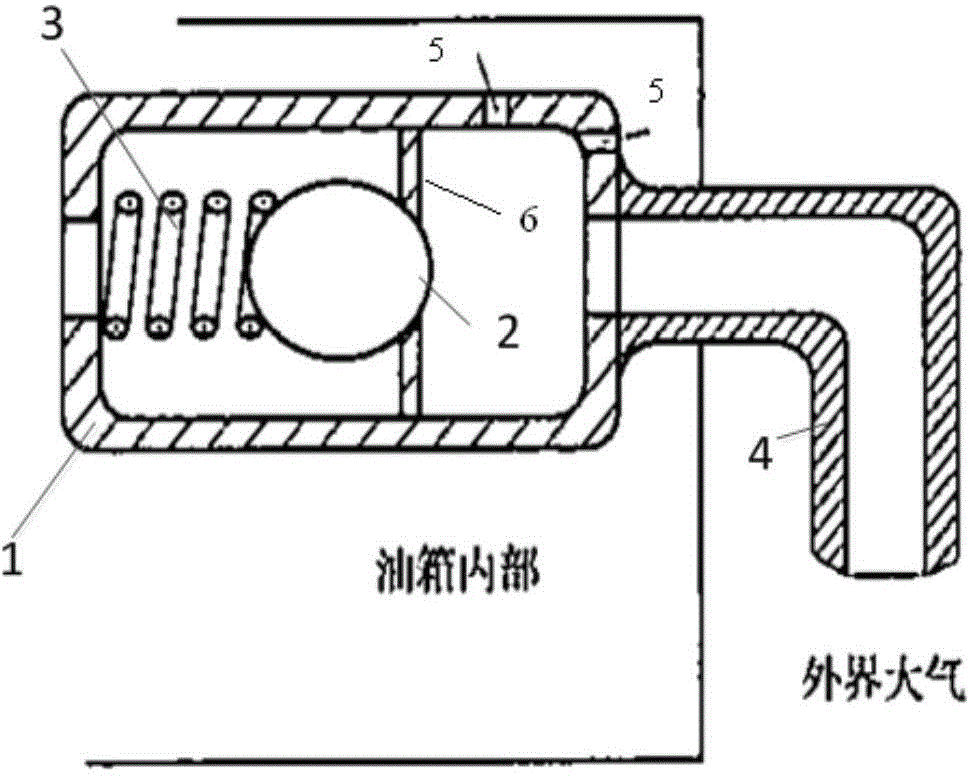
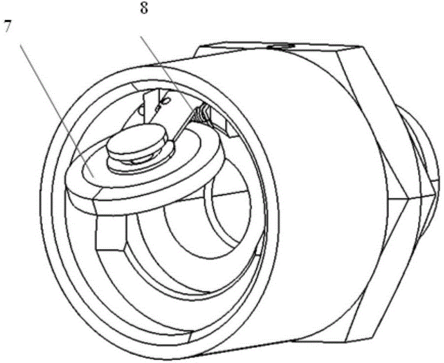
[0015] The specific embodiment of the present invention will be described with reference to the accompanying drawings. Such as figure 1 , figure 2 , The device casing 1 on the device of the present invention is connected together with the ventilation pipe 4 through threads, and the device casing 1 is provided with a ventilation hole 5 . The torsion spring 8 is sleeved on the valve rod of the valve assembly 2, and the valve assembly 2 is fixed on the partition plate 6 through the valve rod. In a natural state, the valve assembly 2 is sealed with the device casing 1 under the force of the torsion spring 3 .
[0016] The diameter of the vent hole 5 on the device casing 1 of the device of the present invention is 1-3 mm. During the flight of the aircraft, when the pressure in the fuel tank is greater than or equal to the atmospheric pressure, the valve assembly 2 seals the through hole of the partition 6 under the force of the torsion spring 8, and exhausts air to the outside ...
PUM
| Property | Measurement | Unit |
|---|---|---|
| Diameter | aaaaa | aaaaa |
Abstract
Description
Claims
Application Information