Mechanical yaw brake

A yaw brake, mechanical technology, applied in the direction of the brake type, axial brake, brake components, etc., can solve the problems of piston wear, engine room oil pollution, oil cylinder oil leakage, etc., to solve the oil leakage problem and improve the service life Long, simple structure effect

Inactive Publication Date: 2014-04-02
CHANGSHA EASTAR MACHINERY
View PDF6 Cites 5 Cited by
  • Summary
  • Abstract
  • Description
  • Claims
  • Application Information

AI Technical Summary

Problems solved by technology

[0002] The hydraulic brake system is installed on a fixed base, which is stationary relative to the brake disc. The diameter of the brake disc is generally more than 2000mm, the thickness is 30mm, and the unevenness of the upper and lower parallel surfaces is more than 2mm. The axial runout of the moving disc, when the brake disc rotates and jumps, the force on the upper and lower calipers of the hydraulic brake is seriously unbalanced, which is transmitted to the piston cylinder, which eventually leads to severe wear of the piston and oil leakage from the cylinder, causing serious oil damage to the engine room. Pollution
Due to the jumping of the horizontal plane of the slewing bearing and the brake disc, the hydraulic brake will cause the brake bolts to be stressed, resulting in bolt breakage, piston explosion and shutdown, and cause corresponding damage to other components in the engine room.

Method used


Image

  • Mechanical yaw brake
  • Mechanical yaw brake
  • Mechanical yaw brake

Examples


Embodiment Construction

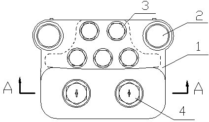
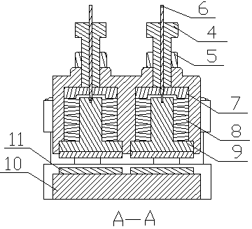
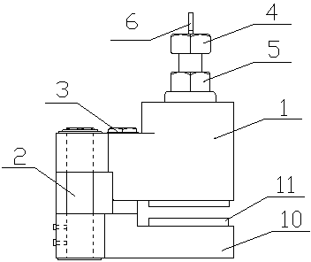
[0014] Such as figure 1 , figure 2 , image 3 with Figure 4 As shown, a mechanical yaw brake includes an upper tong box 1 and a lower tong box 10, and the upper and lower tong boxes are fixedly connected together by five M24×160 bolts 3; The movable pin 2 of the lower clamp box and the lower clamp box; two sets of matching pressing pins 7, top clamping blocks 9 and disc springs 8 are installed in the upper clamp box, and the two ends of the disc spring 8 are respectively pressed against Push the pressing pin 7 and the pressing block 9; above the pressing pin 7, be provided with a lock nut 4 and an adjusting bolt 5 for adjusting the pressing force of the pressing pin 7; The upper end of the jacking block 9, the center of the pressing pin 7 and the locking nut 4 are provided with a matching hole, and a marking rod 6 is installed in the matching hole, and one end of the marking rod 6 is connected to the top tight The block 9 is fixedly connected, and the other end is expose...


PUM


Abstract

The invention discloses a mechanical yaw brake comprising an upper clamp box and a lower clamp box. The upper clamp box and the lower clamp box are fixedly connected together through bolts. The mechanical yaw brake further comprises moving pins penetrating the upper and lower clamp boxes. At least one fitting set of compressing pin, ejector block and disc spring is mounted inside the upper clamp box. Two ends of each disc spring are abutted to the corresponding compressing pin and the ejector block respectively. A locking nut and an adjusting bolt are arranged above each compressing pin. The upper end of each ejector block is provided with a central fitting hole, each compressing pin is provided with a central fitting hole, and each locking nut is also provided with a central fitting hole, wherein a marker rod is disposed in the fitting holes, one end of the marker rod is fixedly connected with the ejector block, the other end of the marker rod is exposed out of the locking nut, and the part, close to the locking nut, of the marker rod is provided with a visual mark line. The mechanical yaw brake is simple in structure, hydraulic oil is not required, and the oil leakage problem is substantially solved; checking pre-tightening force through indication of the marker rods is required only, maintenance is convenient, and the service life of the mechanical yaw brake is long.

Description

technical field [0001] The invention belongs to the field of yaw braking systems of wind power generators, and in particular relates to a mechanical brake. Background technique [0002] The hydraulic brake system is installed on a fixed base, which is stationary relative to the brake disc. The diameter of the brake disc is generally more than 2000mm, the thickness is 30mm, and the unevenness of the upper and lower parallel surfaces is more than 2mm. The axial runout of the moving disc, when the brake disc rotates and jumps, the force on the upper and lower calipers of the hydraulic brake is seriously unbalanced, which is transmitted to the piston cylinder, which eventually leads to severe wear of the piston and oil leakage from the cylinder, causing serious oil damage to the engine room. pollute. Due to the jumping of the horizontal plane of the slewing bearing and the brake disc of the hydraulic brake, the force of the brake bolts will be complicated, resulting in bolt bre...

Claims


Application Information

Patent Timeline
Patent Type & Authority Applications(China)
IPC IPC(8): F16D55/22F16D65/00F16D66/02
Inventor 凌建辉田莉刘细平朱小华
Owner CHANGSHA EASTAR MACHINERY
Why Eureka
Try Eureka