Lens unit and optical communication module group

An optical communication module, lens unit technology, applied in the direction of lens, light guide, optics, etc.

Inactive Publication Date: 2015-03-18
HONG FU JIN PRECISION IND (SHENZHEN) CO LTD +1
View PDF5 Cites 0 Cited by
  • Summary
  • Abstract
  • Description
  • Claims
  • Application Information

AI Technical Summary

Problems solved by technology

[0003] The light emitted by the light-emitting unit enters the optical fiber through a path of a certain length in the lens unit; while the light transmitted by the optical fiber also passes through the path of the same length in the lens unit, and is received by the light-receiving unit. Therefore, the lens unit generally only has one length. path of

Method used


Image

  • Lens unit and optical communication module group
  • Lens unit and optical communication module group
  • Lens unit and optical communication module group

Examples


Embodiment Construction

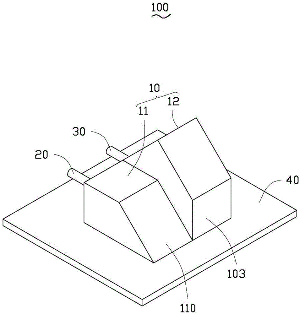
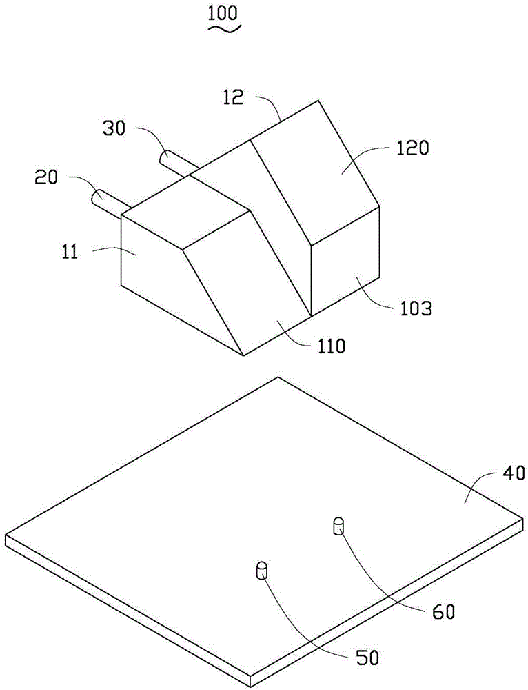
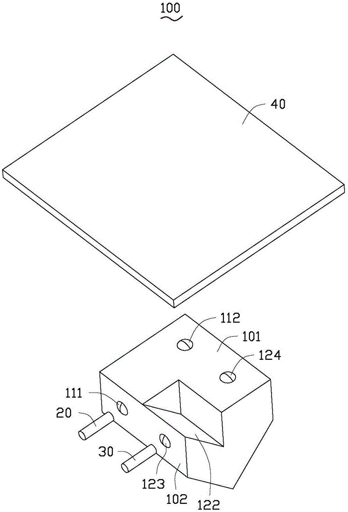
[0016] see figure 1 , figure 2 and image 3 , the optical communication module 100 of the embodiment of the present invention includes a lens unit 10 , a first optical fiber 20 , a second optical fiber 30 , a circuit board 40 , a first optoelectronic unit 50 and a second optoelectronic unit 60 .

[0017] Wherein, the circuit board 40 is a hard board or a soft board, and the first photoelectric unit 50 and the second photoelectric unit 60 are electrically arranged on the circuit board 40. The first photoelectric unit 50 and the second photoelectric unit 60 can be light emitting units (for example, light-emitting diode or laser diode), can also be a light-receiving unit (for example, a photodetector); the lens unit 10 is used to realize the optical coupling between the first optical fiber 20 and the first photoelectric unit 50 and the second optical fiber 30 and the second Optical coupling between photocells 60 .

[0018] The lens unit 10 includes a first part 11 and a secon...


PUM


Abstract

The invention relates to a lens unit comprising a first portion and a second portion. The first portion and the second portion have a common bottom surface and a common first side surface, wherein the bottom surface is perpendicular to the first side surface. The first portion has a first reflection surface that is intersected with the bottom surface and the first side surface; and the included angle is 45 degrees. The second portion has a second side surface parallel to the first side surface; a second reflection surface, a third reflection surface, and a fourth reflection surface are arranged between the first side surface and the second side surface, wherein the second reflection surface and the third reflection surface are perpendicular to and intersected with each other and the fourth reflection surface is parallel to the third reflection surface; the second reflection surface and the first side surface are intersected with each other with the included angel of 45 degrees; and the third reflection surface and the second side surface are intersected with each other with the included angle of 45 degrees. The first reflection surface, the second reflection surface, the third reflection surface, and the fourth reflection surface are used for realizing 90-degree conversion of an optical signal. In addition, the invention also relates to an optical communication module group having the lens unit.

Description

technical field [0001] The invention relates to a lens unit and an optical communication module. Background technique [0002] A traditional optical communication module includes an optical fiber, a photoelectric unit (including a light-emitting unit and a light-receiving unit) and a lens unit. The lens unit is used to couple optical signals between the optical fiber and the photoelectric unit. [0003] The light emitted by the light-emitting unit enters the optical fiber through a path of a certain length in the lens unit; while the light transmitted by the optical fiber also passes through the path of the same length in the lens unit, and is received by the light-receiving unit. Therefore, the lens unit generally only has one length. path of. Contents of the invention [0004] In view of this, it is necessary to provide a lens unit and an optical communication module with paths of different lengths. [0005] A lens unit, comprising a first part and a second part, the f...

Claims


Application Information

Patent Timeline
IPC IPC(8): G02B7/02G02B6/42
CPCG02B17/0856G02B3/02G02B6/4206
Inventor 洪毅
Owner HONG FU JIN PRECISION IND (SHENZHEN) CO LTD
Why Eureka
Try Eureka