Hydraulic type cone crusher

A cone crusher, hydraulic technology, applied in the field of mining equipment, can solve the problems of reducing the service life of the equipment, easy centrifugal separation of the stop push plate, small feeding port and discharging port, etc. The effect of increasing the flow of stone and improving the crushing efficiency

Active Publication Date: 2015-03-25
ZHEJIANG ZHEKUANG HEAVY IND CO LTD
View PDF6 Cites 20 Cited by
  • Summary
  • Abstract
  • Description
  • Claims
  • Application Information

AI Technical Summary

Problems solved by technology

[0003] However, the existing cone crushers have the following disadvantages: 1. At present, the cone crushers are only equipped with a load-bearing frame base, but not equipped with a motor seat for installing a driving motor. When using a machine, a table will be built on one side of the frame base, and the drive motor will be installed on the table, which is very inconvenient for the installation process; 2. The feed inlet and outlet of the existing rack are relatively small, resulting in The stone flow rate of the cone crusher is not large, which affects the production efficiency of the equipment; 3. The eccentric sleeve in the eccentric mechanism is not stable enough, and it is easy to shift axially, and the eccentric bush in the eccentric sleeve is rigidly connected to it, resulting in the eccentric bush and The wear between the movable cone spindle groups is relatively large, which reduces the service life of the equipment; 4. The connection strength of the movable cone spindle groups is not enough, and the movable cone liner is easy to loosen, posing a safety hazard; 5. The hydraulic oil sealing effect in the hydraulic lifting mechanism Poor, and the piston gland used to position the oil seal is easy to fall off when the equipment is running, posing a safety hazard; 6. The stability of the support assembly is insufficient. When the swing speed of the movable cone main shaft group is too fast, the stop push plate is easy to be centrifugally separated. There is a risk of accident

Method used


Image

  • Hydraulic type cone crusher
  • Hydraulic type cone crusher
  • Hydraulic type cone crusher

Examples


Embodiment Construction

[0039] The preferred embodiments of the present invention will be described in further detail below in conjunction with the accompanying drawings.

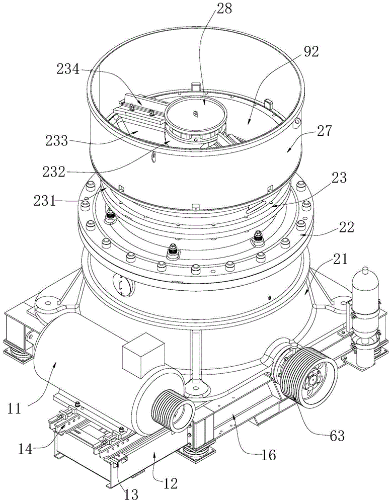
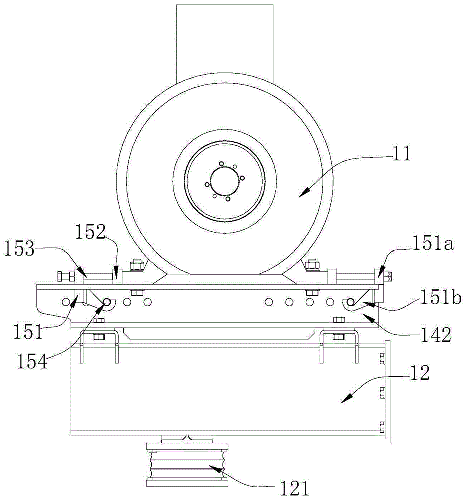
[0040] Such as Figure 1~Figure 14 The shown hydraulic cone crusher includes a machine base, a driving motor 11 and a frame arranged on the machine base, and a transmission mechanism 6, an eccentric mechanism 5, a hydraulic lifting mechanism 7, and a moving mechanism arranged in the frame. Cone spindle group 3 and support assembly 4. The drive motor 11 drives the eccentric mechanism 5 through the transmission mechanism 6, the positioning of the moving cone main shaft group 3 is installed in the eccentric mechanism 5, the hydraulic lifting mechanism 7 is below the moving cone main shaft group 3, the hydraulic lifting mechanism 7 and the moving cone main shaft group 3 They are connected by support assembly 4.

[0041] The following content describes each part of the cone crusher in detail:
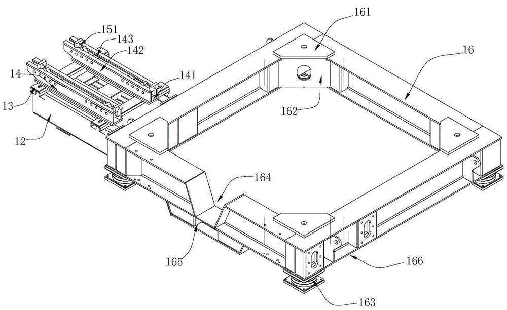
[0042] Machine base

[0043] The fr...


PUM


Abstract

The invention relates to the field of mining equipment, in particular to a hydraulic type cone crusher. The hydraulic type cone crusher comprises a machine base, a driving motor, a machine frame, a transmission mechanism, an eccentric mechanism, a hydraulic lifting mechanism, a moving cone spindle set and a bearing assembly, wherein the driving motor and the machine frame are arranged on the machine base, and the transmission mechanism, the eccentric mechanism, the hydraulic lifting mechanism, the moving cone spindle set and the bearing assembly are arranged in the machine frame. The driving motor drives the eccentric mechanism through the transmission mechanism, and the lower end of the moving cone spindle set is positioned and installed in the eccentric mechanism. The hydraulic lifting mechanism is located below the moving cone spindle set. The hydraulic lifting mechanism and the moving cone spindle set are connected through the bearing assembly. The hydraulic type cone crusher is high in strength, good in stability and convenient to install.

Description

technical field [0001] The invention relates to the field of mining equipment, in particular to a hydraulic cone crusher. Background technique [0002] Cone crusher is a kind of mining machinery used for crushing stone. Its main components include the frame, and the transmission mechanism, eccentric mechanism, hydraulic lifting mechanism, moving cone main shaft group and support assembly arranged in the frame; among them, the eccentric mechanism Connected with the transmission mechanism, the lower end of the movable cone spindle group is positioned and installed in the eccentric mechanism, and the eccentric mechanism drives the movable cone spindle group to rotate and swing; the hydraulic lifting mechanism is located under the movable cone spindle group of the cone crusher to adjust the movable cone spindle The axial height of the group can change the size of the crushing chamber; the support assembly is arranged between the hydraulic lifting mechanism and the movable cone s...

Claims


Application Information

Patent Timeline
Patent Type & Authority Applications(China)
IPC IPC(8): B02C2/04
Inventor 陈利华赵孟军李国强陈炳敏
Owner ZHEJIANG ZHEKUANG HEAVY IND CO LTD
Why Eureka
Try Eureka