Wire collecting device

A collection device and wire technology, applied in the field of collection, can solve problems such as easy removal of wires

Inactive Publication Date: 2015-03-25
WUHU QIUJING FASTENER
View PDF0 Cites 0 Cited by
  • Summary
  • Abstract
  • Description
  • Claims
  • Application Information

AI Technical Summary

Problems solved by technology

[0003] The purpose of the present invention is to provide a wire collecting device, which overcomes the problem in the prior art that it is difficult to make the wires easier to take out when collecting the wires, realizes the collection of the wires and facilitates the taking out of the wires at the same time

Method used


Image

  • Wire collecting device

Examples


Embodiment Construction

[0022] Specific embodiments of the present invention will be described in detail below in conjunction with the accompanying drawings. It should be understood that the specific embodiments described here are only used to illustrate and explain the present invention, and are not intended to limit the present invention.

[0023] In the present invention, unless stated to the contrary, the used orientation words such as "up, down, left, right" usually refer to up, down, left, and right on the outline of the product. "Inside and outside" refer to the inside and outside under the natural conditions relative to the observer. "Far and near" refer to far and near relative to a certain component.

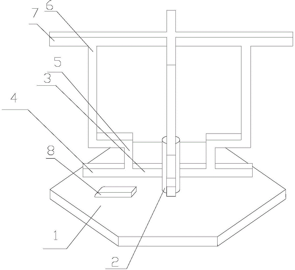
[0024] In a specific embodiment of the wire collecting device of the present invention, the wire collecting device includes: a chassis 1, on which a rotating shaft 2 is arranged;

[0025] A crossbar 3, the crossbar 3 is fixed and runs through the rotating shaft 2 and can rotate with the rot...


PUM


Abstract

The invention discloses a wire collecting device. The wire collecting device comprises a base plate (1), a transverse rod (3) and two vertical rods (5). A rotating shaft (2) is arranged on the base plate (1). The transverse rod (3) is fixed, penetrates through the rotating shaft (2) and can rotate along with the rotating shaft (2). A stop section (4) extends in the length direction of the transverse rod (3). The two vertical rods (5) are fixedly connected with the two ends of the transverse rod (3) respectively. According to the wire collecting device, wire collection is achieved, and meanwhile wires can be conveniently taken out.

Description

technical field [0001] The invention relates to the collection field, in particular to a wire collection device. Background technique [0002] In the field of wire rod production, due to the needs of production, the wire rods must be collected before the next step of operation, and the collected wire rods also need to be easily taken out, so how to collect the wire rods to make the wire rods easier to take out has become an urgent need solved problem. Contents of the invention [0003] The object of the present invention is to provide a wire collecting device, which overcomes the problem in the prior art that it is difficult to make the wires easier to take out when collecting the wires, realizes the collection of the wires and facilitates the taking out of the wires. [0004] In order to achieve the above object, the present invention provides a wire collecting device, the wire collecting device includes: a chassis, the chassis is provided with a rotating shaft; [0005...

Claims


Application Information

Patent Timeline
Patent Type & Authority Applications(China)
IPC IPC(8): B65H75/26B65H75/04
Inventor 陶清明查尚强陶善龙
Owner WUHU QIUJING FASTENER
Why Eureka
Try Eureka