Multi-dimensional and parallel-swing sea wave power generation device

A technology of wave power generation and parallel connection, which is applied in the direction of ocean energy power generation, engine components, machines/engines, etc., can solve the problems affecting the life of the swing shaft, loss, and low power generation efficiency, and achieve good sealing, improved life, and high life. Effect

Inactive Publication Date: 2013-09-18
SHANGHAI JIAO TONG UNIV
View PDF3 Cites 26 Cited by
  • Summary
  • Abstract
  • Description
  • Claims
  • Application Information

AI Technical Summary

Problems solved by technology

[0002] After searching the prior art, it is found that the fan-shaped flume wave power generation device (Chinese Patent No. 2L.200920002647.X) that converts the impact energy of waves into electric energy has the following problems: 1. The fan-shaped flume is located on the shore, and the waves move to the shore A lot of energy has been lost when it reaches the power generation device, and the power generation efficiency is low
2. The fan-shaped water tank is poured on the bank foundation, so in the process of pouring the fan-shaped tank, under the constraints of the terrain and the influence of the ebb and flow, the difficulty of pouring and the amount of work are quite large
The main shaft finally transmits the motion to the generator to realize power generation, but this device has the following disadvantages: 1. When the waves hit the swing plate, the swing shaft will always be impacted, and this rigid shock is repeated, which affects the life of the swing shaft
2. Only when the direction of the wave is perpendicular to the swinging plate, the device can effectively generate electricity, and the direction of the wave is random, so the utilization rate of the wave is low

Method used


Image

  • Multi-dimensional and parallel-swing sea wave power generation device
  • Multi-dimensional and parallel-swing sea wave power generation device
  • Multi-dimensional and parallel-swing sea wave power generation device

Examples


Embodiment Construction

[0036] The following is a detailed description of the embodiments of the present invention: this embodiment is implemented on the premise of the technical solution of the present invention, and provides detailed implementation methods and specific operation processes. It should be noted that those skilled in the art can make several modifications and improvements without departing from the concept of the present invention, and these all belong to the protection scope of the present invention.

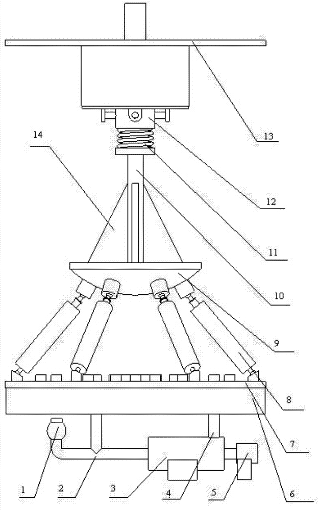
[0037] Such as figure 1 As shown, this embodiment provides a multi-dimensional parallel swing wave power generation device, including a buoyancy tank 40 and a top cover 13 arranged inside the buoyancy tank 40, a three-degree-of-freedom motion pair 12, a swing rod 10, a spring 11, and a rib 14 , upper platform 9, six parallel hydraulic cylinders 8, lower platform 7, mixed oil tank 6, accumulator 1, hydraulic motor 3, generator 5, wherein, top cover 13 is fixedly connected to the boss of ...


PUM


Abstract

The invention discloses a multi-dimensional and parallel-swing sea wave power generation device. A top cover is fixedly connected with the top wall of a buoyancy box, one end of a three-degree-of-freedom movement pair is fixedly connected with the top cover, the other end of the three-degree-of-freedom movement pair is engaged with a swing rod, one end of the swing rod penetrates through the top wall of the buoyancy box and is fixedly connected with an outside device, the other end of the swing rod is fixedly arranged on an upper platform through the support of rib plates, a spring is fixedly connected with a shaft shoulder of the swing rod, six parallel hydraulic cylinders are arranged between the upper platform and a lower platform, piston rods of the six parallel hydraulic cylinders are hinged to the upper platform, cylinder bodies of the six parallel hydraulic cylinders are hinged to the lower platform, the lower platform is fixedly arranged on an oil mixture tank, the oil mixture tank is fixedly connected with the side wall of the buoyancy box, the oil mixture tank is connected with a hydraulic motor through a separating pipe and a return pipe, a generator is connected with the hydraulic motor, the generator and the hydraulic motor are arranged at the bottom of the buoyancy box, and an energy accumulator is connected with the hydraulic motor. The device has the characteristics that the service life is long, and the pollution is little; and while the energy of the sea wave in the transverse swinging is absorbed, the energy of the sea wave in the vertical direction can also be absorbed.

Description

technical field [0001] The invention relates to the technical field of wave power generation devices, in particular to a multi-dimensional parallel swing wave power generation device. Background technique [0002] After searching the prior art, it is found that the fan-shaped flume wave power generation device (Chinese Patent No. 2L.200920002647.X) that converts the impact energy of waves into electric energy has the following problems: 1. The fan-shaped flume is located on the shore, and the waves move to the shore A lot of energy has been lost when it reaches the power generating device, and the power generation efficiency is low. 2. The fan-shaped sink is poured on the bank foundation. Therefore, in the process of pouring the fan-shaped tank, under the constraints of the terrain and the influence of the ebb and flow, the pouring difficulty and the amount of work are quite large. [0003] Investigate the existing swing-type wave power generation device, use the new patent...

Claims


Application Information

Patent Timeline
Patent Type & Authority Applications(China)
IPC IPC(8): F03B13/14
CPCY02E10/30
Inventor 马春翔陈康郑茂琦陈伟聪高峰王志波
Owner SHANGHAI JIAO TONG UNIV
Why Eureka
Try Eureka