
a back bolt

A technology of back bolts and sleeves, applied in the direction of connecting components, pins, covering/lining, etc., can solve problems such as inability to install in place, deformation, sleeves are easy to fall out, etc., and achieve the effect of improving production efficiency

Active Publication Date: 2017-06-16
斯泰科技(杭州)有限公司 +2
View PDF1 Cites 0 Cited by
  • Summary
  • Abstract
  • Description
  • Claims
  • Application Information

AI Technical Summary

Problems solved by technology

[0002] At present, the existing back bolts used in the curtain wall of the building envelope, in order to prevent the screw from rotating, are all provided with anti-slip bosses on the vertebral body at the bottom of the screw, but before the expansion element is stretched, the expansion element and the bottom of the screw There is still a distance from the anti-slip boss on the vertebral body, so even if it is installed by hand, it cannot completely avoid the anti-slip boss on the vertebral body. When the expansion element is stretched, due to the The anti-slip boss cannot be avoided, which will cause a certain part of the expansion element to stand on the anti-slip boss and cannot be installed in place and deformed, or the expansion element will stretch along the surface of the anti-slip boss to generate local large stress to support the plate. Cracks, or when the expansion element is thinner than the sheet, it will be stuck in the ground bottom hole smaller than the largest part of the reaming hole to form false expansion, and eventually slippage will occur. Therefore, there are many safety problems that the plate will fall after installation. For example, the invention patent (application number: 201080057289.0) "fastener" disclosed by PCT in China is the anchor bolt of this structure type.
[0003] In addition, with the soaring labor costs in our country and the impact of the construction industry on the tighter and tighter deadlines, our country is entering the era of machines replacing labor in an all-round way. However, the existing back bolts, considering that the scattered parts are not conducive to installation, the average production time A complete set of pre-assembly is used, and the nuts are unscrewed during installation, which will take a lot of work and time; and during installation, due to the influence caused by the expansion element being pushed by the boss or the extension element extending along the surface of the boss, there is still a problem. It is impossible to use a highly automated installation method, and can only be installed by manually dislocating the anti-slip boss and the expansion element and then tapping the installation; and for the plate with the back bolt installed, the sleeve is easy to fall out during the handling process. If the workers no longer load it, there is a hidden danger that the plate will crack and fall due to the formation of torsional stress

Method used


Image

  • a back bolt
  • a back bolt
  • a back bolt

Examples


Embodiment Construction

[0036] In order to further explain the technical means and functions adopted by the present invention to achieve the intended invention purpose, the structure, features and functions of the present invention will be described in detail below in conjunction with the accompanying drawings and preferred embodiments.

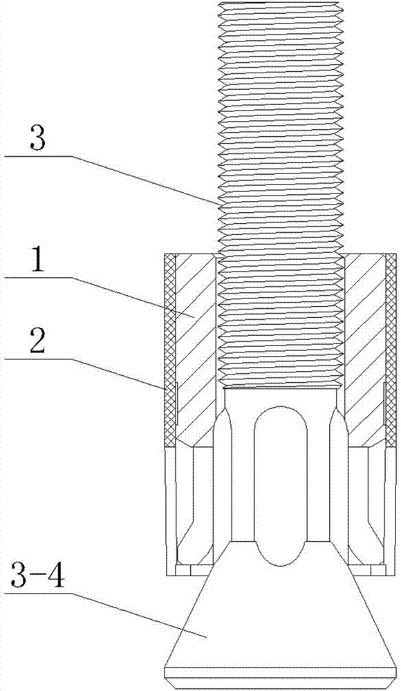
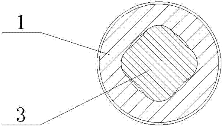
[0037] The back bolt described in the present invention has a structure such as figure 1 , figure 2 As shown, it specifically includes the anchor rod 3, the sleeve 1, the lower end of the sleeve 1 is provided with an expansion section, the upper part of the anchor rod 3 is provided with a receiving section 3-1, the receiving section 4-1 is provided with an external thread, and the lower end is provided with a cone section 3 -4, a connecting section 3-2 is set between the receiving section 3-1 of the anchor rod 3 and the cone section 3-4, and several strip ribs 3-3 are arranged on the outer peripheral surface of the connecting section 3-2. 3-3 is arranged along the...


PUM


Abstract

The invention discloses a back bolt which comprises an anchor rod and a sleeve, wherein an expansion section is arranged at the lower end of the sleeve; a carrying section is arranged at the upper part of the anchor rod, a cone section is arranged at the lower end of the anchor rod, a connecting section is arranged between the carrying section of the anchor rod and the cone section, a plurality of strip-shaped ribs are arranged on the outer circumferential surface of the connecting section and are arranged in the axial direction of the anchor rod; in the process of mounting the back bolt, and the strip-shaped ribs are matched with the expansion section to block relative rotation between the anchor rod and the sleeve; after entering the sleeve, the strip-shaped ribs form a tight fit with the sleeve to block the backward slip of the sleeve.

Description

technical field [0001] The invention relates to a back bolt, which is used for the decoration of various buildings with dry-hanging boards, and is anchored and connected through the back of the board, so it is called "back bolt". It is suitable for the use of dry-hanging curtain walls such as building envelope structures with high anti-vibration requirements and anti-braking impact subway stations, as well as for firewalls. It is also suitable for installation in concrete or other wall materials, as a fixed connection with undercut anchor bolts Other components are used. Background technique [0002] At present, the existing back bolts used in the curtain wall of the building envelope, in order to prevent the screw from rotating, are all provided with anti-slip bosses on the vertebral body at the bottom of the screw, but before the expansion element is stretched, the expansion element and the bottom of the screw There is still a distance from the anti-slip boss on the verte...

Claims


Application Information

Patent Timeline
Patent Type & Authority Patents(China)
IPC IPC(8): F16B13/06E04F13/22
CPCE04F13/22F16B13/06
Inventor 徐跃华周桂云徐洁媛李擘陈新兵孙学红张清华
Owner 斯泰科技(杭州)有限公司
Learn More