Air duct system, air supply method thereof and air conditioner with air duct system

An air duct and wind tunnel technology, applied in the field of air ducts, can solve problems such as low air output efficiency, achieve the effects of stable air supply, good energy conservation and environmental protection, and increase the scope of air supply

Active Publication Date: 2015-03-25
GD MIDEA AIR-CONDITIONING EQUIP CO LTD
View PDF6 Cites 10 Cited by
  • Summary
  • Abstract
  • Description
  • Claims
  • Application Information

AI Technical Summary

Problems solved by technology

[0002] In the air duct structure in the prior art, grid-shaped air inlets and outlets are directly arranged on the casing, and the air outlet efficiency is low

Method used


Image

  • Air duct system, air supply method thereof and air conditioner with air duct system
  • Air duct system, air supply method thereof and air conditioner with air duct system
  • Air duct system, air supply method thereof and air conditioner with air duct system

Examples


Embodiment 1

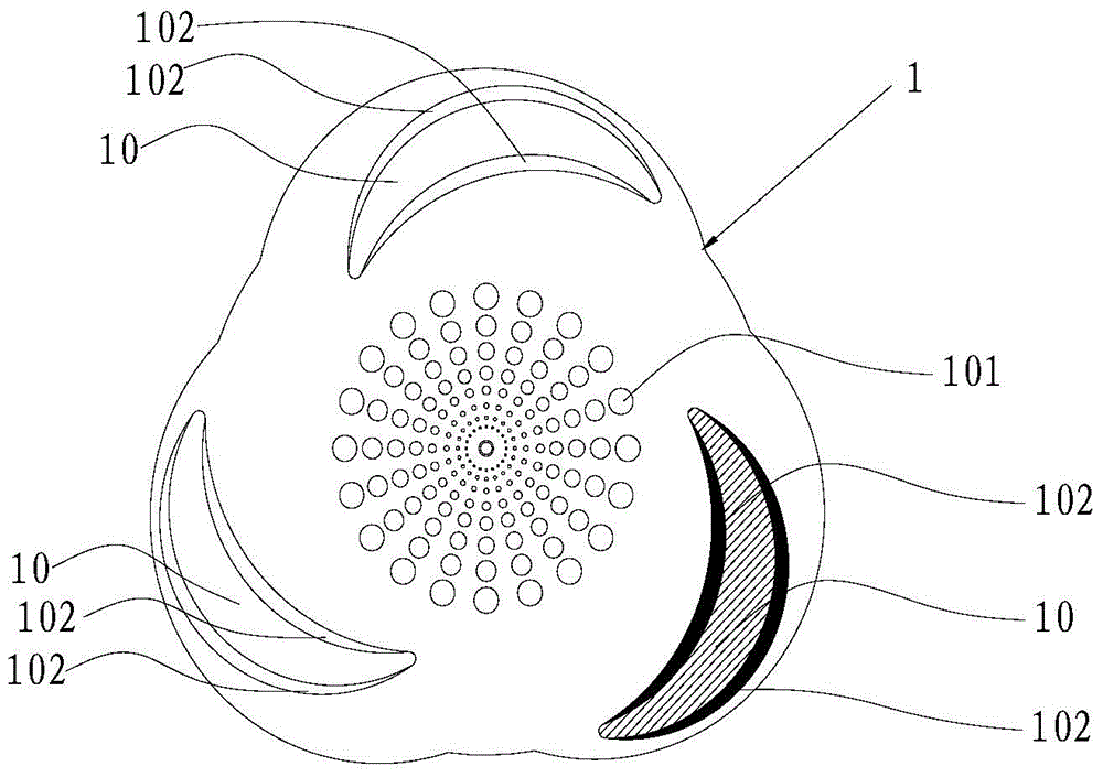
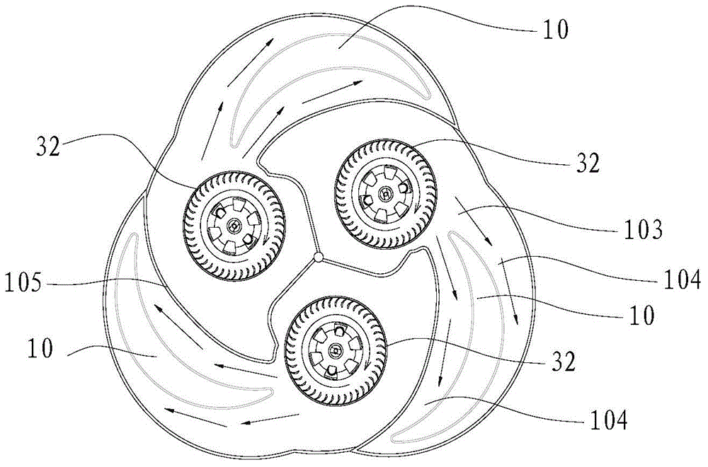
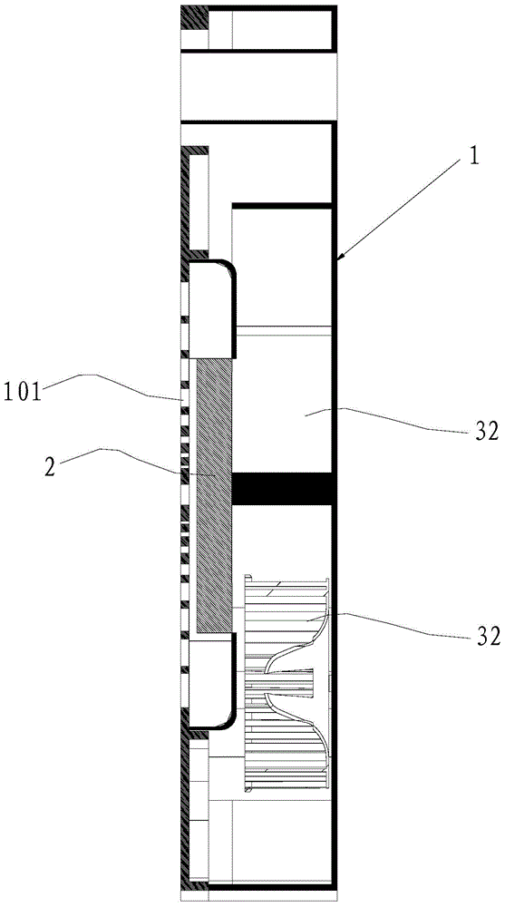
[0039] Such as Figure 1 to Figure 5 As shown, an air duct system provided by the embodiment of the present invention includes a casing 1, the casing 1 has an air inlet 101, and at least two wind wheels 32 are arranged in the casing 1, and each wind wheel 32 is connected with a corresponding The motor 31 and the wind wheel 32 can be fixedly connected to the rotating shaft of the motor 31, and each wind wheel 32 can rotate at the same time, also can run or stop separately, and the speed of each wind wheel 32 can also be adjusted independently. There are at least two airflow passages 103 in the casing 1, and each wind wheel 32 corresponds to at least one airflow passage 103. The casing 1 is provided with at least one wind tunnel 10 through the front and rear corresponding to the airflow passage 103. The wind tunnel 10 An air outlet 102 is provided on the side wall or the periphery for blowing air out to generate negative pressure at the wind tunnel 10 , and the air outlet 102 co...

Embodiment 2

[0048] In this example, if Image 6 As shown, specifically, each airflow passage 103 is correspondingly provided with at least two wind tunnels 10, and each wind tunnel 10 side wall or periphery is provided with an air outlet 102 for blowing out the airflow to generate negative pressure at the wind tunnel 10. , the utilization rate of the airflow channel 103 is high.

Embodiment 3

[0050] On the basis of Example 2, such as Figure 7 As shown, deflectors 106 may be provided between the wind tunnels 10 in the same airflow channel 103 to make the air volumes of the air outlets 102 and the wind tunnels 10 equal.


PUM


Abstract

The invention belongs to the technical field of air ducts, and discloses an air duct system, an air supply method of the air duct system and an air conditioner with the air duct system. Air flow blown out from all air outlets flows forwards to enable negative pressure regions to be formed on the front sides of all air tunnels, and under the effect of all the negative pressure regions, air on the rear sides of the air tunnels is sucked to penetrate through the air tunnels, so that the air is blown out forwards with the air flow blown out from the air outlets. Due to the fact that air has certain viscosity, when the air flow is blown out from the air outlets, the air flow carries adjacent air flow to flow forwards together, the air supply effect at the air flow center is enhanced, moreover, air around the air tunnels is supplemented due to the effect of negative pressure, the air supply range is expanded, the air supply effect which is at least multiple times the air inlet capacity of air inlets is formed through the principles of the aerodynamics, the energy efficiency utilization rate is high, the air flow does not need to be cut by fan blades, the air supply amount is stable and even, human bodies can feel more comfortable, and the air supply effect is good.

Description

technical field [0001] The invention belongs to the technical field of air ducts, and in particular relates to an air duct system, an air supply method thereof, and an air conditioner provided with the air duct system. Background technique [0002] In the air duct structure in the prior art, grid-shaped air inlets and outlets are directly arranged on the casing, and the air outlet efficiency is low. Contents of the invention [0003] The object of the present invention is to overcome the shortcomings of the above-mentioned prior art, and provide an air duct system and its air supply method, and an air conditioner with the air duct system, which has high air outlet efficiency. [0004] The technical solution of the present invention is: an air duct system, including a casing, the casing has an air inlet, at least two wind wheels are arranged in the casing, at least two airflow passages are provided in the casing, each The wind wheel corresponds to at least one of the airfl...

Claims


Application Information

Patent Timeline
Patent Type & Authority Applications(China)
IPC IPC(8): F24F13/02F24F13/10
CPCF24F13/02F24F13/10
Inventor 华龙陈良锐
Owner GD MIDEA AIR-CONDITIONING EQUIP CO LTD
Why Eureka
Try Eureka