
Real-time video stitching method based on specified tracking points

A technology for video splicing and real-time video, applied in the video field, can solve the problems of reducing computational complexity, reducing the search range of feature point registration, etc.

Active Publication Date: 2015-03-25
CHINA AEROSPACE TIMES ELECTRONICS CORP
View PDF1 Cites 14 Cited by
  • Summary
  • Abstract
  • Description
  • Claims
  • Application Information

AI Technical Summary

Problems solved by technology

[0004] The technology of the present invention solves the problem: Compared with the traditional method of feature point registration, using the tracking method to register feature points reduces the search range of feature point registration and reduces the computational complexity

Method used


Image

  • Real-time video stitching method based on specified tracking points
  • Real-time video stitching method based on specified tracking points
  • Real-time video stitching method based on specified tracking points

Examples


Embodiment Construction

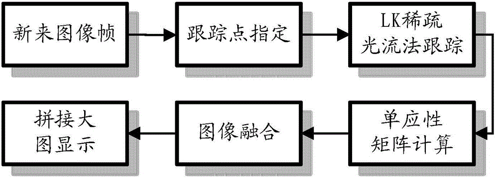
[0013] In the following, the present invention will be further introduced in conjunction with the accompanying drawings from the aspects of tracking point designation, LK sparse optical flow method tracking, homography matrix calculation, image fusion and comparison and analysis of experimental results.

[0014] 1. Tracking point designation

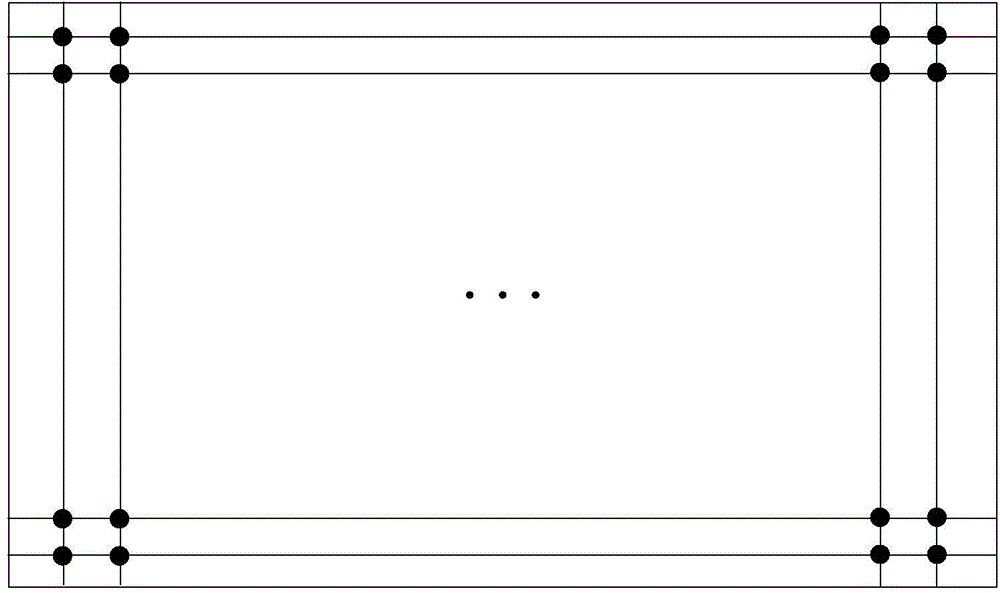
[0015] Suppose the image width is w and the height is h, and m×m points are uniformly selected from the image as tracking points (see figure 2 , the intersection shown in the figure is the specified tracking point). Since the boundary points are not used as tracking points, the set of selected points is P = { ( w m + 1 , h m + 1 ) , ( ...


PUM


Abstract

The invention provides a real-time video stitching method based on specified tracking points. The video stitching method comprises the steps that some pixel points are directly selected from an image and used as tracking points, and the calculation time and effect of stitching are controlled by controlling the number of the tracking points and the distribution of the tracking points. Compared with the prior art, the real-time video stitching method based on the specified tracking points has the advantages that the feature point extraction process is omitted, some pixel points are directly extracted from the image to be used as the tracking pints, the number and the distribution of the tracking points can be controlled, and therefore the calculation time and effect can be controlled partially.

Description

technical field [0001] The invention belongs to the field of video, and in particular relates to a real-time video mosaic technology realized by a method for calculating an image registration matrix by tracking a designated point. Background technique [0002] Video stitching is to splice video image frames together to form a large picture, and you can see the panorama of the shooting area corresponding to the video. UAV video stitching is one of the basic steps in UAV information processing and the basis for subsequent steps such as map product output. Video splicing often faces the contradiction between splicing effect control and real-time performance. To achieve a good splicing effect, it is difficult to achieve real-time splicing; otherwise, the continuous splicing time is short and the effect is poor. Since small UAVs are easily disturbed by the external environment, their posture changes are relatively drastic. At the same time, the image quality of the cameras carri...

Claims


Application Information

Patent Timeline
IPC IPC(8): G06T7/00G06T5/00
CPCG06T3/4038G06T7/246G06T2207/10016G06T2207/20221G06T2207/30181
Inventor 向永红张国勇姜梁孙浩惠马祥森郭茜王家星
Owner CHINA AEROSPACE TIMES ELECTRONICS CORP
Learn More