
LED spliced screen structure

A technology of splicing screen and adjustment seat, which is applied in the direction of instruments, identification devices, etc., which can solve the problems of difficult positioning of display modules, imperfect display of LED splicing screens, and waste of time.

Inactive Publication Date: 2015-03-25
GUANGDONG VTRON TECH CO LTD
View PDF6 Cites 7 Cited by
  • Summary
  • Abstract
  • Description
  • Claims
  • Application Information

AI Technical Summary

Problems solved by technology

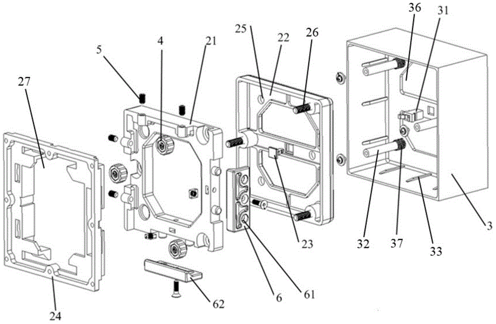
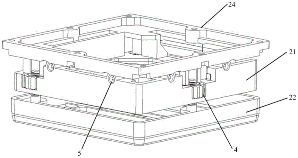
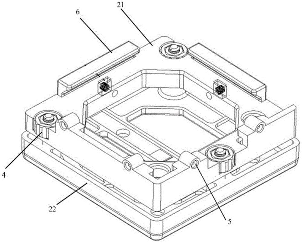
[0005] The embodiment of the present invention provides a structure of an LED splicing screen, which solves the need to dismantle the cabinet on the back of the LED splicing screen or LED display module in the prior art, and repair the problematic display module. The positioning of the display module is difficult, avoiding the technical problems of wasting time and low maintenance efficiency, and the technical problems of imperfect display of the LED splicing screen caused when the multiple display modules of the LED splicing screen are not on the same plane. occur

Method used


Image

  • LED spliced screen structure
  • LED spliced screen structure
  • LED spliced screen structure

Examples


Embodiment Construction

[0036] The embodiment of the present invention provides a structure of an LED splicing screen, which solves the need to dismantle the cabinet on the back of the LED splicing screen or LED display module in the prior art, and repair the problematic display module. The positioning of the display module is difficult, avoiding the technical problems of wasting time and low maintenance efficiency, and the technical problems of imperfect display of the LED splicing screen caused when the multiple display modules of the LED splicing screen are not on the same plane. occur.

[0037] In order to make the purpose, features and advantages of the present invention more obvious and understandable, the technical solutions in the embodiments of the present invention will be clearly and completely described below in conjunction with the accompanying drawings in the embodiments of the present invention. Obviously, the following The described embodiments are only some, not all, embodiments of t...


PUM


Abstract

The embodiment of the invention relates to an LED spliced screen structure which solves the technical problems that in the prior art, due to the design that an LED spliced screen or a box body on the back of an LED display module needs to be disassembled to maintain the display module which goes wrong, positioning of the display module is difficult, time is wasted, the maintenance efficiency is low, and display of the LED spliced screen is not complete due to the fact that a plurality of display module bodies of the LED spliced screen are not located on the same plane. The LED spliced screen structure comprises a movable module movably connected with a positioning module, the movable module comprises an adjusting seat and a fixing component, a clamping component is arranged at the bottom of the fixing component, holes are formed in the adjusting seat and are used for longitudinal adjusting components to penetrate through to be connected with the fixing component, and thus the adjusting seat can conduct up and down position moving relative to the fixing component in the perpendicular direction. An elastic clamping seat is installed in a box body of the positioning module, and the elastic clamping seat and a clamping component arranged at the bottom of the fixing component are clamped through the cooperation of elastic force.

Description

technical field [0001] The invention relates to the technical field of LED splicing screens, in particular to a structure of an LED splicing screen. Background technique [0002] Due to its light-emitting characteristics, LED (light-emitting diode) has gradually moved from the increasingly mature lighting field, such as LED lights, to the technical field of LED display. The LED display is made by welding or mounting several RGB three-color LED particles The full-color LED display is realized on the PCB substrate. With the development of LED technology, the LED splicing display also emerges as the times require. The LED splicing display is realized by splicing several LED display modules into an overall frame. Several RGB three-color LED particles are soldered or mounted on the PCB substrate of each LED display module, and a box for connecting wiring is provided on the back of each LED display module or the back of the entire LED splicing screen. [0003] At present, in the ...

Claims


Application Information

Patent Timeline
IPC IPC(8): G09F9/33
CPCG09F9/33
Inventor 陈政升余延益
Owner GUANGDONG VTRON TECH CO LTD
Learn More