ECP construction method and installation device

An installation device and installation assistance technology, applied in the direction of metal processing, etc., can solve the problems of not being able to adapt to deformation cracks, falling off and falling high-altitude parabolic objects, etc., and achieve the effects of improving efficiency, facilitating installation and removal, and improving safety

Pending Publication Date: 2022-04-29
BEIJING URBAN CONSTR GROUP
View PDF0 Cites 0 Cited by
  • Summary
  • Abstract
  • Description
  • Claims
  • Application Information

AI Technical Summary

Problems solved by technology

[0005] In order to make up for the deficiencies of the existing technology and solve the problem that the existing ECP construction method cannot adapt to the earthquake and the deformation cracks of the building itself, so it may fall off and cause the danger of high-altitude parabolic objects, the present invention proposes an ECP construction method and installation device

Method used


Image

  • ECP construction method and installation device
  • ECP construction method and installation device
  • ECP construction method and installation device

Examples


Embodiment 1

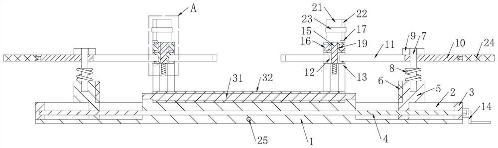
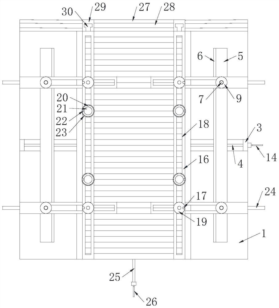
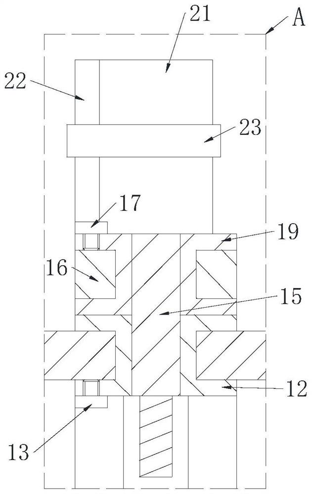
[0035] see Figure 1-4As shown, an ECP construction installation device includes a drilling bottom plate 1, a second threaded shaft 25, a second handle 26 and an installation auxiliary unit; the hole on the drilling bottom plate 1 is threadedly inserted with the second threaded shaft 25; One end of the second threaded shaft 25 is sleeved with a second handle 26; the other end of the second threaded shaft 25 is rotatably sleeved with a synchronous plate 27; the synchronous plate 27 is provided with a synchronous slot 28; the synchronous There is a second slider 29 symmetrically fastened and slidably connected in the groove 28; a third slider 30 is connected to the second slider 29 by slotting and sliding; the third slider 30 is vertically fixed with a vertical Plate 16; the vertical plate 16 is provided with a vertical groove 18; a plurality of third sliding sleeves 20 are fastened and slidably connected in the vertical groove 18; a fixed shaft is fixedly connected to the third...

Embodiment approach

[0052] see Figure 5 As shown in Comparative Example 1, as another embodiment of the present invention, a plurality of support columns 33 are affixed to the lower surface of the drilling floor 1; during operation, the drilling floor 1 and the ground Keep the distance, so as to facilitate the rotation of the first handle 14 and the second handle 26, and it is more convenient to use the palm to carry, and there are more stressed parts; and it is convenient to fix with the ground through the support column 33, thereby ensuring the cutting device in the installation method It can work stably and normally.

[0053] The working principle is to place the ECP board on the protective sleeve 32 and push it forward so that the ECP board is flush with the synchronization board 27, and the second threaded shaft 25 can be driven to rotate by turning the second handle 26, which can drive the limit Rotate the synchronous plate 27 sleeved on the second threaded shaft 25 to move along the axia...


PUM


Abstract

The invention belongs to the field of building construction, and particularly relates to an ECP construction method and installation device which comprises a drilling bottom plate, a second threaded shaft, a second handle and an installation auxiliary unit. A second threaded shaft is inserted into an opening in the drilling bottom plate in a threaded manner; one end of the second threaded shaft is sleeved with a second handle; the other end of the second threaded shaft is rotationally sleeved with a synchronous plate. A synchronous groove is formed in the synchronous plate; second sliding blocks are symmetrically connected into the synchronous groove in a buckled and sliding mode. The second sliding block is slotted, buckled and connected with a third sliding block in a sliding manner; a vertical plate is vertically and fixedly connected to the third sliding block; a vertical groove is formed in the vertical plate; by means of the design of the method, the function of elastic connection between the ECP and the wall is achieved, the problem that danger is generated due to the fact that in rigid connection between an existing ECP and the wall, the ECP and the wall possibly fall off after an earthquake and deformation and cracking of the wall occur is solved, and the safety of ECP installation is improved.

Description

technical field [0001] The invention relates to the field of building construction, in particular to an ECP construction method and an installation device. Background technique [0002] Installation refers to the process of combining multiple components. The correctness of the installation method is related to the performance of the finished product after installation. [0003] ECP refers to vacuum extruded cement board, which is a new type of cement board, which has the functions of sound insulation, antifreeze and fire resistance; it is a multifunctional cement board. [0004] The existing ECP construction method cannot adapt to the earthquake and the deformation cracks of the building itself, so there may be a risk of falling off and causing high-altitude parabolic objects; therefore, an ECP construction method and installation device are proposed to address the above problems. Contents of the invention [0005] In order to make up for the deficiencies of the existing ...

Claims


Application Information

Patent Timeline
IPC IPC(8): B26F1/16B26D7/01B26D7/26
CPCB26F1/16B26D7/01B26D7/26Y02E10/20
Inventor 张洁孟阳袁国旗薛金涛
Owner BEIJING URBAN CONSTR GROUP
Why Eureka
Try Eureka