A tunnel air purification equipment

A technology for tunnel air and purification equipment, which is applied in the directions of external electrostatic separator, electrostatic separation, electrode cleaning, etc., can solve the problems of occupying tunnel space, difficult air purification, and squeezing the installation space of the purifier, so as to improve the processing air volume and improve the Effect of purifying air volume

Active Publication Date: 2018-03-02
KELAN TECHNICS ENVIRONMENTAL PROD CO LTD
View PDF6 Cites 0 Cited by
  • Summary
  • Abstract
  • Description
  • Claims
  • Application Information

AI Technical Summary

Problems solved by technology

There is a problem with this scheme: due to the limited space in the upper part of the tunnel, and it is often an irregular structure (such as a semi-cylindrical shape), and the purifier is generally a cuboid structure. The number or volume of purifiers that can be installed is very limited, so many purification units must be installed along the axis of the tunnel to achieve better air purification performance
The purification air volume of a single purifier is often much smaller than that of the jet fan installed in the tunnel, and it cannot be used in conjunction with the existing jet fan. If multiple purification devices are connected in parallel through the air duct to draw air, the duct will occupy valuable space in the upper part of the tunnel. , to further squeeze the installation space of the purifier
Therefore, this solution is difficult to efficiently purify the air in the tunnel; in addition, the scattered installation of multiple equipment is not convenient for equipment maintenance and repair;
[0004] Another solution is to build a bypass tunnel, leading the flue gas from the tunnel to the bypass tunnel for purification and then sending it back to the tunnel or discharging it to the atmosphere outside the tunnel after purification. This solution solves the problem of the first solution. problem, but the owner must invest in a bypass tunnel, which requires a large capital investment

Method used


Image

  • A tunnel air purification equipment
  • A tunnel air purification equipment
  • A tunnel air purification equipment

Examples


Embodiment Construction

[0022] In order to make the object, technical solution and advantages of the present invention more clear and definite, the present invention will be further described in detail below with reference to the accompanying drawings and examples.

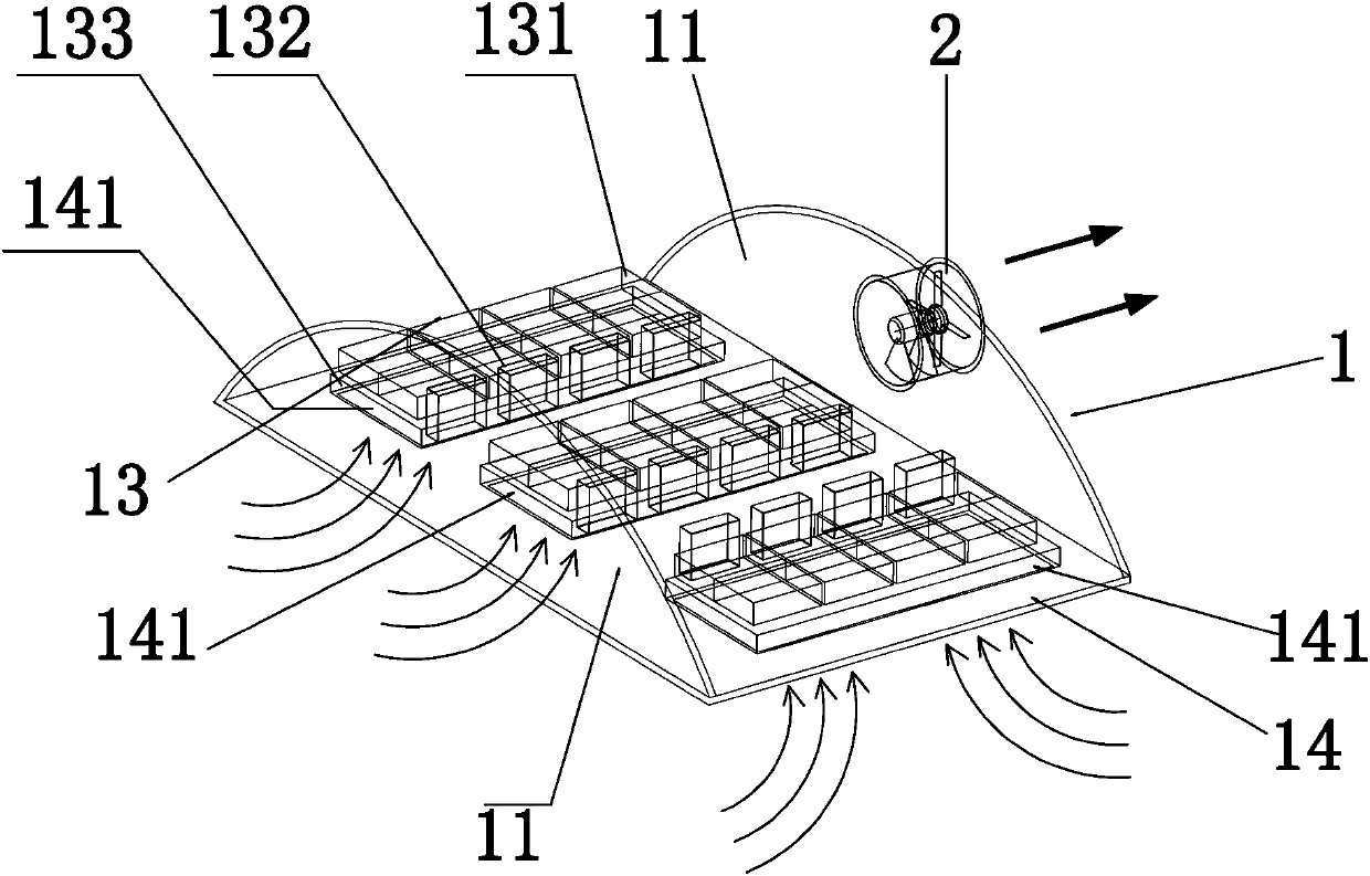
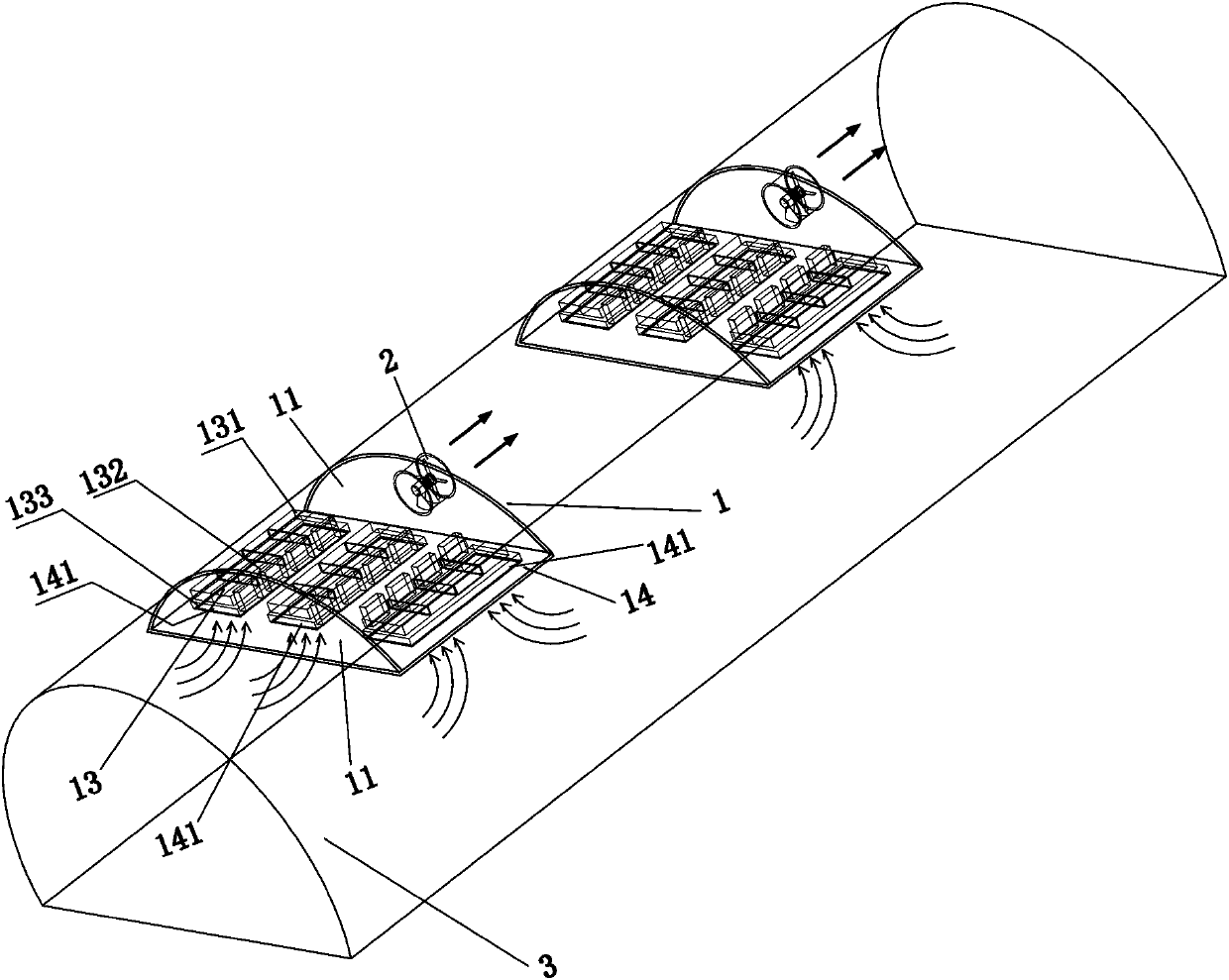
[0023] Such as figure 1 Shown, a kind of tunnel air cleaning equipment, comprises the clean room 1 that is used to purify air and the suction fan 2 that draws the air out of the clean room, and the suction fan 2 is arranged on one of the fan-shaped side panels 11 of the clean room 1; the clean room is A clean room 1 is formed by isolating the irregular (such as semi-cylindrical) space on the upper part of the tunnel; the clean room 1 includes two fan-shaped side panels 11 that fit and seal the top surface of the tunnel, a ceiling load-bearing surface 14, And several groups of cleaning units 13 for purifying air, wherein an exhaust fan 2 is installed on a fan-shaped side panel 11, and the other fan-shaped side panel 11 is in sealing conne...


PUM


Abstract

The invention discloses a tunnel air purification device. The tunnel air purification device comprises a purification chamber for purifying air, a suction opening for installing a suction fan and a draught fan, wherein the purification chamber comprises two side panels and a ceiling bearing surface at the bottom of the side panel; the suction opening is arranged on one side panel of the purification chamber; the draught fan is installed on the suction opening while the other side panel is in sealing connection with the top surface of the tunnel. The ceiling bearing surface is provided with ventilation openings for guiding tunnel air into the purification chamber; each ventilation opening is provided with a purification unit. The beneficial effect of the tunnel air purification device is that each ceiling bearing surface is provided with multiple purification units so that the multiple purification units can operate in parallel under the finite cross section area of the tunnel; the wind disposal capacity of the entire purification device is greatly improved on the premise that the purifying efficiency is ensured, thus the tunnel air purifying effect is improved.

Description

technical field [0001] The invention relates to the field of air purification equipment, in particular to tunnel air purification equipment. Background technique [0002] With the increase of vehicles, the emission of vehicle exhaust has become an important cause of smog weather, which causes poor air quality and low visibility. Especially in the tunnel, the exhaust gas emitted by a large number of vehicles, coupled with the poor ventilation of the tunnel, the PM2.5 in the tunnel seriously exceeds the standard, and the visibility of the air is reduced, which affects traffic safety and the health of drivers and passengers; in tunnels of underground rail transit All kinds of dust generated by the friction between the wheels and the tracks also pollute the tunnels and platforms. Therefore, it is very necessary to purify the air in the tunnel. [0003] There are two existing tunnel air purification schemes. One is to hang a certain number of purification equipment and fans on ...

Claims


Application Information

Patent Timeline
Patent Type & Authority Patents(China)
IPC IPC(8): B03C3/04B03C3/78B03C3/34
Inventor 尤今尤毅
Owner KELAN TECHNICS ENVIRONMENTAL PROD CO LTD
Why Eureka
Try Eureka