Ultrashort-flow technique for industrial dust removal

An ultra-short, process technology, applied in dispersed particle separation, chemical instruments and methods, dispersed particle filtration, etc., can solve the problems of large floor space, high resistance, high energy consumption, and achieve less maintenance workload, energy consumption and low energy consumption. Low noise and small footprint

Inactive Publication Date: 2013-03-06
无锡市东方工业节能环保有限公司
View PDF4 Cites 0 Cited by
  • Summary
  • Abstract
  • Description
  • Claims
  • Application Information

AI Technical Summary

Problems solved by technology

The entire dust removal system has long process, high resistance, many process links, many s

Method used


Image

  • Ultrashort-flow technique for industrial dust removal
  • Ultrashort-flow technique for industrial dust removal

Examples


Embodiment Construction

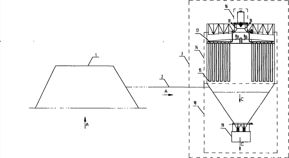
[0036] Below, combine figure 2 Specifically illustrate the implementation of the present invention:

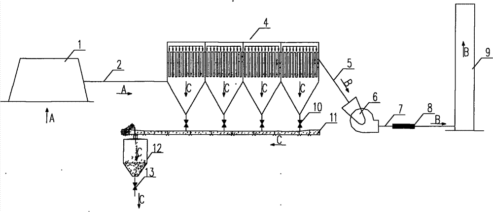
[0037] The ultra-short industrial dust removal process is composed of a collection hood 1, a flue gas pipeline 2 and a large-scale integrated dust removal unit 3, which realizes the collection, purification, noise control of the existing industrial dust removal system flue gas, clean gas emission and dust-free dust Ash discharge and other functions. Under the negative pressure of the dust removal system, the industrial flue gas is collected by the collection hood 1, enters the integrated dust removal unit 3 through the pipe 2, and separates the gas and dust through the filter bag 15 in the flue gas purification unit 14, and the filtered clean gas Under the action of the negative pressure of the induced air exhaust unit 16, it is directly discharged into the atmosphere. The dust collected on the outside of the filter bag 15 falls into the ash storage and discharge unit 18 un...


PUM


Abstract

The invention relates to an ultrashort process technique for industrial dust removal, belonging to a technique method of an industrial dust removal system. According to the process route, under the negative pressure action of a dust removal system, smoke passes through a dust collecting cover 1, a smoke pipe 2 and a large integrated dust removal unit 3 in sequence, so that all functions of a conventional dust removal system, such as smoke collecting and purification, noise treatment and separated emission of clean gas and dust, can be realized with an ultrashort flow. Through optimizing and simplifying the process procedures of the conventional dust removal system, the technique has the beneficial effects of greatly shortening the process flow, further reducing resistance, energy consumption and noise of the dust removal system, lowering the occupied area, solving the dust flying problem in ash discharge and ensuring reliable running of the system and low maintenance workload.

Description

technical field [0001] The invention relates to an ultra-short process process for industrial dust removal, which belongs to the method for treating industrial smoke and dust pollution and relates to the technical field of dust removal. Background technique [0002] Existing large-scale industrial dust removal system (handling air volume is 100,000m 3 The process flow is mainly as follows: the flue gas is captured by the collection cover 1 under the negative pressure of the dust removal system, and then enters the dust collector 4 through the flue gas pipe 2 for purification; the purified gas passes through the fan inlet pipe 5 , fan 6, fan outlet pipe 7, muffler 8, and finally enter the exhaust tube 9 to be discharged into the atmosphere; the collected dust is transported to the centralized ash bin 12 through the ash unloading valve 10, one-stage or multi-stage conveyor 11, and then sent to the centralized ash bin 12 by The ash unloading device 13 is unloaded into the tran...

Claims


Application Information

Patent Timeline
IPC IPC(8): B01D46/04B01D46/42
Inventor 郑敬鹤冷吟王卫黄兴华
Owner 无锡市东方工业节能环保有限公司
Why Eureka
Try Eureka