Pipeline support group and single pipeline support

A pipeline support and monomer technology, applied in the direction of pipeline support, pipe/pipe joint/pipe fitting, mechanical equipment, etc., can solve the problem of limited installation angle of multiple pipelines, and achieve the effect of solving the limited installation angle

Active Publication Date: 2015-04-01
GREE ELECTRIC APPLIANCES INC OF ZHUHAI
10 Cites 2 Cited by

AI-Extracted Technical Summary

Problems solved by technology

[0004] In view of this, the first object of the present invention is to provide a pipeline support unit, the structural design of the pipeline support ...

Method used

In addition, the first mounting hole 41 is the first bolt hole, and the second bolt hole a can also be provided on the first side plate 1 and the second side plate 5, and the second bolt hole a is positioned at the arc hole b. The inner side, wherein the inner side of the arc-shaped hole b refers to the side where the center of the circle is located. In this way, the second bolt hole a of the first side plate 1 of a pipeline support unit can be fixedly connected with the arc-shaped hole b of another pipeline support unit through bolts, and the first side plate of a pipeline support unit The arc-shaped hole b of 1 is fixedly connected with the second bolt hole a of another pipeline support unit through bolts, so as to make the connection between two adjacent pipeline support units more firm. Rotating a pipeline support unit can ensure that the position of another pipeline support unit adjacent to it remains unchanged. Of course, the second bolt hole a of the first side plate 1 of a pipeline support unit can also be fixedly connected with the second bolt hole a of another pipeline support unit through bolts, and the first bolt hole a of a pipeline support unit The arc-shaped hole b of the side plate 1 is fixedly connected with the arc-shaped hole b of another pipe support unit through bolts. When the second bolt hole a is a circular hole, the center of the second bolt hole a may overlap with the center of the arc-shaped hole b. The bolt passing through the arc-shaped hole b can move along the extension direction of the arc-shaped hole b, so as to adjust the installation angle of the pipeline. The clamp of the intermediate plate 4 and the pipeline may also be fixedly connected through the first installation hole 41 by bolts.
When applying the pipeline support monomer provided by the embod...

Abstract

The invention discloses a pipeline support group and a single pipeline support. The single pipeline support comprises a middle plate, a first side plate and a second side plate, wherein a first installation hole is formed in the middle plate; the middle plate can be fixedly connected with a clamp for a pipeline through the first installation hole; the first side plate and the second side plate are respectively and fixedly connected with the middle plate; the first side plate and the second side plate are in parallel, and are respectively located on two sides of the middle plate; penetrating arc-shaped holes are formed in each of the first side plate and the second side plate. By applying the pipeline support group and the single pipeline support, the fixation of pipelines extending towards different directions can be realized; an included angle between the planes where the middle plates of every two adjacent single pipeline supports are located can be realized through rotation, so that an included angel between the axes of pipelines respectively fixed by the middle plates of the two single pipeline supports can be realized; the problem that the installation angle of multiple pipelines are restricted is solved.

Application Domain

Pipe supports

Technology Topic

EngineeringSupport group

Image

  • Pipeline support group and single pipeline support
  • Pipeline support group and single pipeline support
  • Pipeline support group and single pipeline support

Examples

  • Experimental program(1)

Example Embodiment

[0032] The first object of the present invention is to provide a single pipe support unit whose structural design can effectively solve the problem of limited installation angles of multiple pipes. The second object of the present invention is to provide A pipeline bracket group.
[0033] The technical solutions in the embodiments of the present invention will be clearly and completely described below in conjunction with the accompanying drawings in the embodiments of the present invention. Obviously, the described embodiments are only a part of the embodiments of the present invention, rather than all the embodiments. Based on the embodiments of the present invention, all other embodiments obtained by those of ordinary skill in the art without creative work shall fall within the protection scope of the present invention.
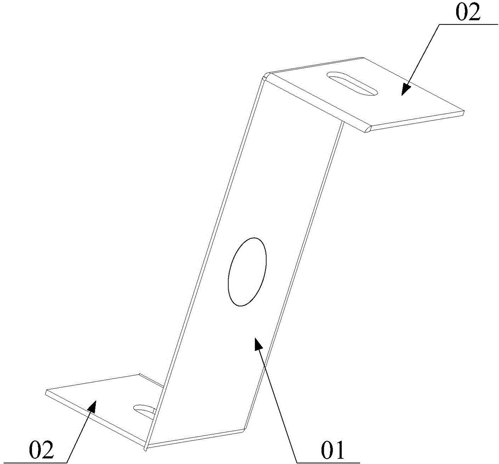
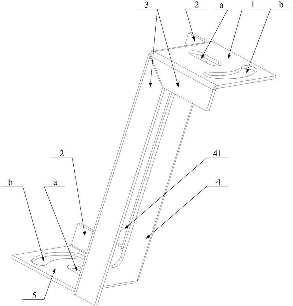
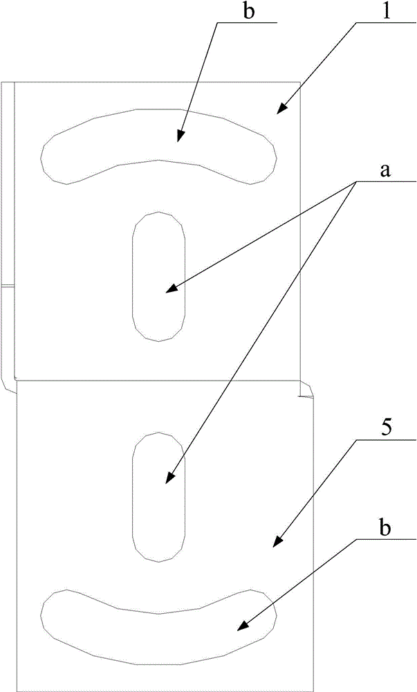
[0034] See Figure 2-Figure 6 The single pipe bracket provided by the embodiment of the present invention is mainly used to fix and install the clamp 6 of the pipe, which includes a middle plate 4, a first side plate 1 and a second side plate 5. Wherein, the intermediate plate 4 is provided with a first mounting hole 41, and the intermediate plate 4 can be fixedly connected to the clamp 6 of the pipeline through the first mounting hole, that is, the clamp 6 can be fixed through the first mounting hole 41 by bolts or other fixing parts. And the middle plate 4 is fixed together. The first side plate 1 and the second side plate 5 are respectively fixedly connected to both ends of the middle plate 4, and the first side plate 1 and the second side plate 5 are parallel to each other, and the first side plate 1 and the second side plate 5 are respectively located Both sides of the middle plate 4. That is, the first side board 1, the second side board 5 and the middle board 4 together form a Z shape, and the angle between the plane where the first side board 1 and the middle board 4 are located is the same as the plane where the second side board 5 and the middle board 4 are located The angles between are equal. The first side plate 1 is inclined to one side of the intermediate plate 4, and the second side plate 5 is inclined to the other side of the intermediate plate 4. Both the first side plate 1 and the second side plate 5 are provided with arc-shaped holes b, that is, the first side plate 1 or the second side plate 5 of a single pipe support can pass through the arc-shaped holes b and The fitting of the fixing member of the hole b is fixedly connected with the first side plate 1 or the second side plate 5 of the base or another pipeline support unit. Since both the first side plate 1 and the second side plate 5 are provided with arc-shaped holes b, the arc-shaped hole b is the extension direction of an arc, so the fixing member passing through the arc-shaped hole b can follow the arc The extension direction of the hole b moves, that is, the pipe support unit can rotate relative to the fixing part passing through the arc hole b, and then the clamp 6 and the pipeline fixed therewith can rotate relative to the fixing part passing through the arc hole b.
[0035] When using the single pipe support unit provided by the embodiment of the present invention, the first side plate 1 and the second side plate 5 are connected and fixed to the base or the first side plate 1 or the second side plate 5 of another pipe support unit Because the first side plate 1 and the second side plate 5 are both provided with arc-shaped holes b, the fixing member passing through the arc-shaped hole b can move along the extending direction of the arc-shaped hole b. When the arc-shaped hole b moves, the entire pipeline bracket rotates relative to the fixed part, and the intermediate plate 4 rotates relative to the fixed part. In this way, the intermediate plate 4 can be rotated to a suitable position and the first side plate 1 and the second side The board 5 is fixed. The clamp 6 of the pipeline is fixedly connected with the intermediate plate 4 through the first mounting hole 41, and the axis of the pipeline is generally arranged in parallel with the intermediate plate 4. In this way, through the rotation of the intermediate plate 4, the pipes in different extension directions can be fixed, the installation angle of the pipe can be adjusted, and the plane of the intermediate plates 4 of the two adjacent pipe supports can be clamped. Therefore, it is realized that the axes of the pipelines fixed by the intermediate plates 4 of the two pipeline brackets can have an included angle, which solves the problem of limited installation angles of multiple pipelines.
[0036] In order to further optimize the above technical solution, the first side plate 1 and the second side plate 5 can both be arranged perpendicular to the middle plate 4, which is more convenient for the installation and fixing of the pipeline support unit. Of course, the angle between the first side plate 1 and the second side plate 5 and the middle plate 4 can also be an acute angle, which is not limited here.
[0037] In addition, the first mounting hole 41 is a first bolt hole, the first side plate 1 and the second side plate 5 may also be provided with a second bolt hole a, and the second bolt hole a is located inside the arc-shaped hole b. The inner side of the arc-shaped hole b refers to the side where its center is located. In this way, the second bolt hole a of the first side plate 1 of a single pipe bracket can be fixedly connected with the arc hole b of the other single pipe bracket through bolts, and the first side plate of a single pipe bracket The arc-shaped hole b of 1 is fixedly connected with the second bolt hole a of another pipeline support unit by bolts, so that the connection between two adjacent pipeline support units is stronger. Rotating one pipeline support unit can ensure that the position of another pipeline support unit adjacent to it remains unchanged. Of course, the second bolt hole a of the first side plate 1 of one pipeline support unit can also be fixedly connected with the second bolt hole a of another pipeline support unit through bolts. The arc-shaped hole b of the side plate 1 is fixedly connected with the arc-shaped hole b of the other pipeline support unit by bolts. When the second bolt hole a is a round hole, the center of the second bolt hole a may overlap the center of the arc-shaped hole b. The bolts passing through the arc-shaped hole b can move along the extension direction of the arc-shaped hole b to adjust the installation angle of the pipeline. The clamp of the intermediate plate 4 and the pipeline can also be fixedly connected through the first mounting hole 41 by bolts.
[0038] In addition, the first bolt hole and the second bolt hole a may both be waist-shaped holes, which makes it easier to adjust the position of the clamp 6 fixed on the intermediate plate 4 and the position of the bolt passing through the second bolt hole a. Of course, the first bolt hole and the second bolt hole a may also be round holes, which are not limited here.
[0039] In order to prevent the clamp 6 from being misaligned with the middle plate 4, the pipe support unit may also include a first baffle 3 that is perpendicular to and fixedly connected to the middle plate 4 and the first side plate 1, and the first baffle 3 is located at The middle board 4 and the first side board 1 are on the same side. That is, the first baffle 3 is located on one side of the pipeline support unit as a whole, and the first baffle 3 is perpendicular to the middle plate 4 and the first side plate 1. When the clamp 6 is connected, it can be pressed against the first baffle 3 . Similarly, it may also include a second baffle 2 that is perpendicular and fixedly connected to the middle plate 4 and the second side plate 5, and the second baffle 2 is located on the same side of the middle plate 4 and the second side plate 5, that is, the second The baffle 2 is entirely located on the other side of the pipeline support unit, and the second baffle 2 is perpendicular to the middle plate 4 and the second side plate 5, and the clamp 6 is connected to the second baffle 2.
[0040] Based on the pipeline stent monomers provided in the above embodiments, the present invention also provides a pipeline stent set that includes a plurality of pipeline stent monomers, wherein the pipeline stent monomers are those in the above embodiments The first side plate 1 of one of the two adjacent pipe support monomers and the second side plate 5 of the other can be fixedly connected through the first mounting hole 41. Since the pipeline support group adopts the pipeline support monomer in the above embodiment, please refer to the above embodiment for the beneficial effects of the pipeline support group.
[0041] Preferably, the first mounting hole 41 is a first bolt hole, and the first side plate 1 and the second side plate 5 of the pipeline support unit may also be provided with a second bolt hole a, and the second bolt hole a is located in the arc Inside the hole b. The inside of the arc-shaped hole b refers to the side where its center is located. In addition, the two adjacent pipeline support units are the first pipeline support unit and the second pipeline support unit respectively, and the second bolt hole a of the first side plate 1 of the first pipeline support unit can be The arc hole b or the second bolt hole a of the second pipeline bracket is connected by bolts by bolts. When the installed two pipelines are parallel to each other and in the same vertical plane, the second bolt hole a of the first side plate 1 of the first pipeline support unit can be connected to the second pipeline support unit through the bolts. The arc-shaped holes b are connected by bolts.
[0042] Wherein, in order to facilitate the rotation of the pipe support unit relative to the bolts connected to it, the second bolt hole a may cover the center of the arc hole b, that is, the second bolt hole a covers the center line of the arc hole b. The central angle of the inner arc of the arc-shaped hole b is 60° and the radius is 40 mm, and the central angle of the outer arc of the arc-shaped hole b is 100° and the radius is 30 mm. The second bolt hole a is a waist-shaped hole, and its length is arranged along the radial direction of the arc-shaped hole b.
[0043] The first side plate 1, the second side plate 5, and the middle plate 4 may all be stainless steel plates, and the three have an integrated structure.
[0044] The various embodiments in this specification are described in a progressive manner. Each embodiment focuses on the differences from other embodiments, and the same or similar parts between the various embodiments can be referred to each other.
[0045] The foregoing description of the disclosed embodiments enables those skilled in the art to implement or use the present invention. Various modifications to these embodiments will be obvious to those skilled in the art, and the general principles defined in this document can be implemented in other embodiments without departing from the spirit or scope of the present invention. Therefore, the present invention will not be limited to the embodiments shown in this document, but should conform to the widest scope consistent with the principles and novel features disclosed in this document.

PUM

no PUM

Description & Claims & Application Information

We can also present the details of the Description, Claims and Application information to help users get a comprehensive understanding of the technical details of the patent, such as background art, summary of invention, brief description of drawings, description of embodiments, and other original content. On the other hand, users can also determine the specific scope of protection of the technology through the list of claims; as well as understand the changes in the life cycle of the technology with the presentation of the patent timeline. Login to view more.
Why Eureka
Try Eureka