Communication device and relay device
A technology of communication devices and relay devices, which is applied in the direction of transmission systems, electrical components, instruments, etc., and can solve problems such as uneven communication traffic
Inactive Publication Date: 2015-04-01
MITSUBISHI ELECTRIC CORP
6 Cites 2 Cited by
AI-Extracted Technical Summary
Problems solved by technology
[0014] In addition, in the automatic meter inspection system for smart meters, there are times when there ...
Method used
[0372] When sending commissions for messages from other applications, the relay device has been instructed to adjust the priority to improve the priority of the message sent,
[0455] In this way, in this embodiment, since the message transmitting and receiving device 20 operates by adjusting t...
Abstract
A relay device (30) receives downstream messages to be sent to a smart meter, stores the received downstream messages, selects, on the basis of the levels of priority of the downstream messages, a high-priority downstream message to be sent to the smart meter with priority among the stored downstream messages, and sends the high-priority downstream message to the smart meter. A message transmission unit (21) sends a downstream message for which a level of priority has been specified, to the relay device (30). A priority level adjustment section (242) specifies an extraction condition used to extract a downstream message for which the level of priority is to be adjusted. The priority level adjustment section (242) also extracts a downstream message that satisfies the extraction condition, and generates a priority level adjustment message that instructs the relay device (30) to select a high-priority downstream message with a level of priority different from the level of priority already set for the extracted downstream message being given to the extracted downstream message. The message transmission unit (21) sends the priority level adjustment message to the relay device (30).
Application Domain
TransmissionElectric digital data processing
Technology Topic
Telecommunications equipmentReal-time computing +3
Image
Examples
- Experimental program(2)
Example Embodiment
[0068] Implementation mode 1.
[0069] In this embodiment, an automatic meter look-up system for smart meters will be described.
[0070] In this embodiment, the message transmitting and receiving device installed at the center judges the progress of the message communication, and outputs an instruction to adjust the priority to the relay device.
[0071] Then, the relay device adjusts the priority according to the instruction from the message sending and receiving device.
[0072] Through these steps, effective and extremely fine-grained priority control is possible.
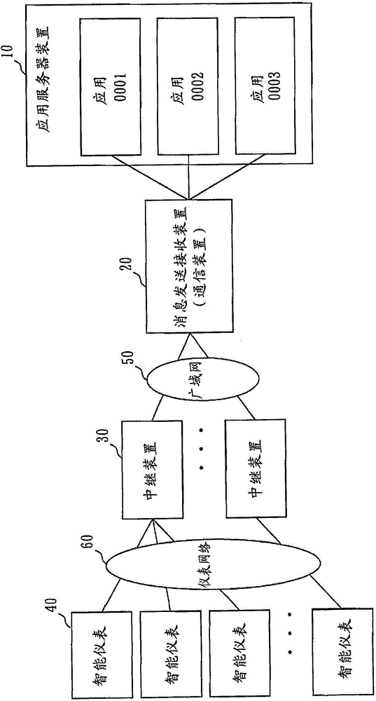
[0073] figure 1 It is a schematic diagram of the smart meter automatic meter inspection system of this embodiment.
[0074] exist figure 1 In the automatic meter look-up system for smart meters, smart meters 40, relay devices 30, message sending and receiving devices 20, and application server devices 10 are connected through a tree-structured network.
[0075] The smart meter 40 measures the consumption of electricity, gas, tap water, etc., between one or more applications operating on the application server device 10, via the message sending and receiving device 20, and between the message sending and receiving device 20 and the smart meter 40. The relay device 30 equipped between carries out message communication.
[0076] The smart meter 40 corresponds to an example of a terminal device.
[0077] In the application server device 10, applications related to automatic table lookup work.
[0078] The application server device 10 transmits a message transmission request (hereinafter also simply referred to as "transmission request") to the message transmission and reception device 20 by executing the application.
[0079] The application server device 10 transmits a message transmission request to the message transmission and reception device 20 , and requests the message transmission and reception device 20 to send messages to the plurality of smart meters 40 .
[0080] In addition, the application server device 10 receives a message from the smart meter 40 from the message transmitting and receiving device 20 .
[0081] The application server device 10 corresponds to an example of a high-level device.
[0082] The message sending and receiving device 20 controls message communication with the application on the application server device 10 and the relay device 30 .
[0083] More specifically, the message sending and receiving device 20 receives a message sending request from the application server device 10 .
[0084] In the message transmission request, one or more transmission messages are included.
[0085] In addition, sending a message is also referred to as a downlink message.
[0086] The message transmitting and receiving device 20 extracts the transmission message from the message transmission request, and transmits the extracted transmission message to the relay device 30 .
[0087] In the transmission message, the ID (Identifier, identifier) of the message transmission request, that is, the transmission request ID and the priority specified by the message transmission request are set.
[0088] In addition, the message transmitting and receiving device 20 receives the received message from the smart meter 40 from the relay device 30 , and transmits the received received message to the application server device 10 .
[0089] In addition, the received message is also referred to as an uplink message.
[0090] In addition, the message sending and receiving device 20 adjusts the priority regarding sending a message and receiving a message.
[0091] The message transmitting and receiving device 20 corresponds to an example of a communication device.
[0092] The relay device 30 relays messages with the smart meter 40 .
[0093] More specifically, the relay device 30 receives downlink messages from the message sending and receiving device 20, accumulates the received downlink messages in queues according to priority, and preferentially sends the downlink messages stored in the queue with the highest priority to Smart Meter40.
[0094] The downlink messages accumulated in the queue with the highest priority, that is, the downlink messages preferentially sent to the smart meter 40 are also referred to as priority downlink messages.
[0095] In addition, the relay device 30 receives uplink messages from a plurality of smart meters 40, stores the received uplink messages in queues according to priority, and preferentially sends downlink messages stored in the queue with the highest priority to message sending and receiving. device 20.
[0096] An uplink message accumulated in the highest priority queue, that is, an uplink message preferentially transmitted to the message transmitting and receiving device 20 is also referred to as a priority uplink message.
[0097] figure 2 It is a system configuration diagram showing a configuration example of the message transmitting and receiving device 20 according to this embodiment.
[0098] exist figure 2 Among them, the priority control processing unit 24 performs priority control of message communication.
[0099] The transmission request accepting unit 26 receives a message transmission request from the application server device 10 , extracts a transmission message addressed to the smart meter 40 from the message transmission request, and transfers the extracted transmission message to the priority control processing unit 24 .
[0100] The message temporary storage unit 27 temporarily stores the plurality of transmission messages extracted by the transmission request acceptance unit 26 when the transmission request acceptance unit 26 receives a message transmission request including transmission messages to a plurality of smart meters 40 .
[0101] The timer unit 25 provides the timing at which the transmission message is fetched from the message temporary storage unit 27 and transferred to the priority control processing unit 24 .
[0102] The message transmission unit 21 receives the transmission message from the priority control processing unit 24 and transmits the transmission message to the relay device 30 .
[0103] In addition, the message transmission unit 21 also functions as an instruction command transmission unit as will be described later.
[0104] The reception request accepting unit 22 receives a message reception request including one or more reception messages from the relay device 30 , and transfers the message reception request to the priority control processing unit 24 .
[0105] In addition, the reception request accepting unit 22 corresponds to an example of a message receiving unit.
[0106] The message distribution unit 28 transmits the message reception request received from the priority control processing unit 24 to the application server device 10 .
[0107] The load information storage unit 23 stores load information periodically transmitted from the relay device 30 and message processing capability information for each model of the relay device.
[0108] In addition, in Embodiment 2, the detail of the load information storage part 23 is demonstrated.
[0109] The priority adjustment data storage unit 29 stores priority adjustment data referred to by the priority control processing unit 24 .
[0110] In addition, the priority control processing unit 24 is composed of a plurality of downstream queues 241 , a plurality of upstream queues 244 , a priority adjustment unit 242 , and a progress information management unit 243 .
[0111] The downstream queue 241 is a queue for storing downstream messages from the application server device 10 to the relay device 30 , that is, downstream messages to the smart meter 40 extracted by the transmission request accepting unit 26 .
[0112] A downstream queue 241 is provided for each priority.
[0113] The upstream queue 244 is a queue for storing upstream messages from the relay device 30 to the application server device 10 , that is, upstream messages from the smart meter 40 .
[0114] Upstream queues 244 are provided for each priority.
[0115] The progress information management unit 243 manages, for each transmission request ID, the number of transmission messages sent by the message transmission unit 21, the number of reception messages received by the reception request acceptance unit 22, the message reception speed of the reception messages, the number of remaining reception messages, and the number of transmission requests. Progress information of message communication such as the time and the remaining time until the reception deadline time.
[0116] The priority adjustment unit 242 performs priority adjustment based on the progress information.
[0117] The priority adjustment unit 242 analyzes the progress information, and designates extraction conditions for extracting downlink messages to be adjusted in priority.
[0118] More specifically, the priority adjustment unit 242 selects a specific transmission request ID, and designates an extraction condition for extracting a downlink message in which the selected transmission request ID is set.
[0119] Then, the priority adjustment unit 242 generates an instruction command (hereinafter referred to as a "priority adjustment message") that instructs the relay device 30 to extract the downlink message in which the selected transmission request ID is set, and to respond to the extracted downlink message. The message selects the priority downlink message using a priority different from the priority described in the downlink message.
[0120] The priority adjustment message is transmitted from the message transmission unit 21 to the relay device 30 .
[0121] In the case of a two-way message, the same transmission request ID and priority as those of the downlink message are set in the uplink message as well.
[0122] When the priority adjustment unit 242 selects the transmission request ID used for the two-way message, the priority adjustment message is also applied to the uplink message.
[0123]That is, the priority adjustment message further includes an instruction to extract an uplink message in which a corresponding transmission commission ID is set, and use a priority different from the priority set in the uplink message for the extracted uplink message. Select Priority Uplink Messages.
[0124] In addition, the downlink message in the two-way message is a downlink message requesting a response from the smart meter 40, and corresponds to a response request downlink message.
[0125] In addition, the priority adjustment unit 242 corresponds to an example of an extraction condition specifying unit and an instruction command generating unit.
[0126] In addition, the downstream queue 241 and the upstream queue 244 of the priority control processing unit 24 are constituted by a plurality of queues for each priority, but may be realized by a single queue.
[0127] In this case, one downlink queue 241 is divided into areas for each priority, and the downlink message input from the transmission request accepting unit 26 is stored in the corresponding priority area.
[0128] Similarly, one uplink queue 244 is divided into areas for each priority, and uplink messages input from the reception request accepting unit 22 are stored in the corresponding priority areas.
[0129] In addition, the downstream queue 241 and the upstream queue 244 may be realized by one queue.
[0130] In this case, one queue is divided into an area for downlink messages and an area for uplink messages, and further, an area for downlink messages is divided for each priority, and an area for uplink messages is divided for each priority .
[0131] Next, the work will be described.
[0132] First, the basic operation of the message transmitting and receiving device 20 when a downlink message is transmitted from the application server device 10 to the relay device 30 will be described.
[0133] A plurality of applications operate in the application server device 10 , and the application requests the message transmitting and receiving device 20 to transmit a message to the smart meter 40 during the process being executed.
[0134] The content of the message depends on the processing executed by the application, and includes, for example, a control message to the smart meter 40 , an information acquisition request from the smart meter 40 , and the like.
[0135] The form of requesting the message sending by the application to the message sending and receiving device 20 is, for example, Figure 11 like that.
[0136] The message transmission request is composed of a header portion including information necessary for controlling message communication, and a data portion including one or more transmission messages of the transmission request and a transmission destination ID.
[0137] When transmitting a transmission message to the smart meter 40, the meter ID of the smart meter 40 of the transmission destination is put in the transmission destination ID.
[0138] In the header part, for example, application ID, message type, size of sent message, total number of sent messages, time limit for receiving response message, and priority are included.
[0139] The application ID uniquely indicates the application that has requested to send the message.
[0140] The message class indicates the class of the sent message (one-way message or two-way message).
[0141] The unit transmission message size indicates the size of data including one transmission message and transmission destination ID.
[0142] The total number of transmission messages indicates the total number of transmission messages included in the data portion of the message transmission request.
[0143] The response message reception deadline time indicates the time when the application accepts the response (uplink message) from the smart meter 40 to the transmission message (response request downlink message).
[0144] A priority is an application-specified priority in communication for sending messages.
[0145] The data section includes a set of the total number of sent messages, the body of the sent message, and the destination ID specifying the destination.
[0146] In the message transmission and reception device 20, the transmission request accepting unit 26 accepts a message transmission request from an application.
[0147] The transmission request accepting unit 26 numbers the transmission request ID of the received message transmission request.
[0148] In addition, when the data part of the received message transmission request includes only one set of the transmission destination ID and the transmission message, the transmission request accepting unit 26 converts the message transmission request into Figure 13 The downlink message in the format shown is forwarded to the priority control processing unit 24 .
[0149] The downlink message includes a destination ID, a transmission request ID, a message type, a transmission message size, a response message reception deadline, and a priority as a header part, and a transmission message included in a message transmission request as a data part.
[0150] The sender ID, message type, send message size, response message reception deadline time, and priority of the header part are the message send request ( Figure 11 ) contained in the value.
[0151] The transmission request ID is a value of the transmission request accepting unit 26 number when accepting the message transmission request.
[0152] On the other hand, when the data portion of the received message transmission request includes a plurality of sets of destination IDs and messages, the sending request accepting unit 26 divides them into sets of each destination ID and message.
[0153] Then, the transmission request accepting unit 26 generates, for each set of the transmission destination ID and the transmission message, Figure 13 Downlink messages of the form shown.
[0154] Thereafter, the transmission request accepting unit 26 stores each generated downlink message in the message temporary storage unit 27 .
[0155] In addition, a message sending request including a plurality of sending messages is called a composite message sending request, and a message sending request including a plurality of bidirectional sending messages (response request downlink messages) is called a composite response request message sending request.
[0156] Next, the transmission request accepting part 26 calculates the interval time when forwarding the downlink message to the priority control processing part 24 based on the total number of messages to be sent contained in the header part and the response message reception deadline, and sets the interval in the timer part 25 time.
[0157] When the response message reception deadline is not specified, the transmission request accepting unit 26 transfers all downlink messages generated based on the transmission message included in the message transmission request to the priority control processing unit 24 .
[0158] The interval time may be obtained by, for example, dividing the time obtained by subtracting the remaining time required for the response from the remaining time until the response message reception deadline, by the total number of transmitted messages.
[0159] Alternatively, predetermined intervals may be used.
[0160] The timer unit 25 sends a timing signal notifying the arrival of the forwarding time to the transmission request accepting unit 26 for each set interval time.
[0161] The transmission request accepting unit 26 that has received the timing signal takes out one downlink message from the message temporary storage unit 27 , and transfers the taken out downlink message to the priority control processing unit 24 .
[0162] In the priority control processing unit 24 , the transmission message forwarded from the transmission request accepting unit 26 is inserted at the end of the queue of the corresponding priority in the downlink queue 241 .
[0163] The message transmission unit 21 fetches the transmission message from the top of the queue with the highest priority among the downlink queues 241 .
[0164] When the queue with the highest priority is empty, the send message is fetched from the head of the queue with the second highest priority.
[0165] Next, the message transmission unit 21 reads the destination ID from the extracted transmission message, and Figure 5 The shown meter relay device correspondence table searches for a relay device ID corresponding to a corresponding transmission destination ID, and transmits a transmission message to the relay device 30 corresponding to the found relay device ID.
[0166] Next, the basic operation of the message transmitting and receiving device 20 when transmitting a message in the uplink direction from the relay device 30 to the application server device 10 will be described.
[0167] The relay device 30 transmits a message reception request including one or more uplink messages to the message transmitting and receiving device 20 .
[0168] The message in the uplink direction is a message received by the relay device 30 from the smart meter 40, and is, for example, a message indicating an event that occurs regularly or irregularly in the smart meter 40, or a message for a message from an application (response request downlink message). Respond to the message.
[0169] The form of the message receiving request received by the message sending and receiving device 20 from the relay device 30 is, for example, as follows: Figure 12 like that.
[0170] The message reception request is composed of a header section including information necessary for controlling message communication, and a data section including one or more received messages and a source ID.
[0171] When receiving a message from the smart meter 40, the meter ID of the smart meter 40 of the sending source is put in the sending source ID.
[0172] The header part includes, for example, a sending request ID or an application ID, a message type, a unit received message size, a total number of received messages, a response message receiving deadline, and a priority.
[0173] The sending request ID is used when the uplink message is a response message to a response request downlink message.
[0174] In the column of the transmission request ID, describe the transmission request ID ( Figure 13 ) the same value.
[0175] The application ID is used when the uplink message is a message sent from the smart meter 40 (not a response message in response to a request for a downlink message).
[0176] The application ID uniquely indicates the application to which the uplink message is transmitted.
[0177] In addition, in Figure 13 The downlink message in which the application ID is not described is exemplified in , but when the application ID is described in the downlink message, the same application ID as that in the uplink message as response data may be described.
[0178] The message class indicates the class of the received message (one-way message or two-way message).
[0179] The unit received message size indicates the size of data including one received message and the source ID.
[0180] The total number of received messages indicates the total number of received messages included in the data portion of the message reception request.
[0181] The response message reception deadline indicates the time when the application accepts the deadline for receiving the message.
[0182]When the received message is a response message to a response request downlink message, in the column of the response message reception time limit, describe the response message reception time limit described in the response request downlink message ( Figure 13 ) the same value.
[0183] The priority indicates the priority in the communication of the received message.
[0184] When the received message is a response message to a response request downlink message, in the priority column, describe the priority level described in the response request downlink message ( Figure 13 ) the same value.
[0185] The data section includes a set of the total number of received messages, the body of the received message, and the source ID indicating the source.
[0186] In the message transmission and reception device 20 , the reception request accepting unit 22 accepts a message reception request from the relay device 30 .
[0187] The reception request accepting unit 22 transfers the message reception request to the priority control processing unit 24 as it is, when the data part of the received message reception request includes only one set of the sender ID and the received message.
[0188] When the data part of the accepted message reception request includes a plurality of sets of the sender ID and the received message, the reception request accepting unit 22 divides the received message into sets of the sender ID and the received message.
[0189] Then, the reception request accepting unit 22 adds the information of the header portion of the message reception request and the transmission source ID to the received message for each set of the transmission source ID and the reception message, and adds the information of the header portion and the transmission source ID to the received message. The received message is forwarded to the priority control processing unit 24 .
[0190] The priority control processing unit 24 inserts the reception message forwarded from the reception request accepting unit 22 at the end of the queue of the corresponding priority in the upstream queue 244 .
[0191] The message distribution unit 28 fetches the received message from the head of the queue with the highest priority among the upstream queues 244 .
[0192] When the queue with the highest priority is empty, the received message is fetched from the head of the queue with the second highest priority.
[0193] Next, the message distribution unit 28 reads out the transmission request ID or the application ID from the received received message, and distributes the received message to the corresponding application.
[0194] Next, operations of the progress information management unit 243 and the priority adjustment unit 242 of the priority control processing unit 24 of the message transmitting and receiving device 20 will be described.
[0195] The progress information management unit 243 manages the data of the priority information table of the priority adjustment data storage unit 29 .
[0196] Figure 4 An example of the priority information table is shown.
[0197] The record of the priority information table is made according to the request unit for sending the message from the application.
[0198] The data items in the priority information table include application ID, sending request ID, sending request time, priority, communication direction, sending number, receiving number, last receiving number, receiving speed, remaining number of received messages, and priority adjustment Index, receiving deadline time.
[0199] In the column of the application ID, the ID of the application that is the source of the message transmission request, that is, the application ID described in the message transmission request is described.
[0200] In the column of the transmission request ID, a transmission request ID that is uniquely numbered at the time of accepting the message transmission request is described.
[0201] In the priority column, the priority specified by the application, that is, the priority described in the message transmission request is described.
[0202] In the column of the communication direction, the communication direction of the message described in the message transmission request, ie, bidirectional or unidirectional, is described.
[0203] In the column of the number of transmissions, the number of messages transmitted as downlink messages from the message transmission unit 21 among transmission messages commissioned in the message transmission request is described.
[0204] In the column of the number of receptions, the number of messages whose responses are received by the reception request accepting unit 22 among the transmission messages commissioned in the message transmission request is described.
[0205] In the column of the previous reception number, when the reception number is updated, the reception number before the update is described.
[0206] The value of the last reception number is used to calculate the reception speed.
[0207] In the column of reception speed, the number of received messages per unit time is described.
[0208] In the column of the remaining number of received messages, the number of received messages to be received after the present is described.
[0209] In the column of the priority adjustment index, an index indicating adjustment of the priority is described.
[0210] In the column of the reception deadline time, the time at which a response to the response request downlink message must be received by the application is described.
[0211] Among them, the number of receptions, the number of previous receptions, the reception speed, and the time of the reception deadline are used only when the communication direction is bidirectional.
[0212] The progress information management unit 243 is called when the transmission request accepting unit 26 receives a message transmission request from the application, and creates a new record in the priority information table describing the transmission request ID of the transmission request receiving unit 26 number.
[0213] At this time, the progress information management unit 243 takes out the application ID, the response message reception deadline time, and the priority from the header portion of the message sending request, and writes the application ID, the reception deadline time, and the priority in the corresponding records of the priority information table. columns of .
[0214] In addition, the progress information management unit 243 extracts the message type, identifies the communication direction, and writes it in the data item of the communication direction.
[0215] Also, when the communication direction is bidirectional, the progress information management unit 243 takes out the total number of sent messages and writes it in the column of the number of remaining received messages.
[0216] When the communication direction is one-way, "0" (zero) is written in the column of the number of remaining received messages.
[0217] In addition, the progress information management unit 243 writes "0" (zero) in the columns of the number of transmissions, the number of receptions, the number of previous receptions, and the priority adjustment index.
[0218] The progress information management unit 243 is called every time a transmission message is transmitted from the message transmission unit 21 of the message transmission and reception device 20, and increments the number of transmissions recorded in the corresponding transmission request ID.
[0219] Also, the progress information management unit 243 is called every time the reception request accepting unit 22 of the message transmitting and receiving device 20 receives a received message, increments the number of received messages recorded in the corresponding transmission request ID, and decrements the number of remaining received messages.
[0220] In addition, the progress information management unit 243 receives a timing signal from the timer unit 25 at certain intervals, for example, every 1 minute, calculates the current reception speed for a bidirectional transmission request in the communication direction, and updates the reception speed of the priority information table. column.
[0221] At this time, the progress information management unit 243 copies the data in the column of the reception number to the column of the previous reception number before updating the column of the reception speed.
[0222] The reception speed is obtained by dividing the difference between the number of receptions and the number of previous receptions by the interval of the timing signal.
[0223] The priority adjustment unit 242 uses the data in the priority information table to determine whether the priority needs to be adjusted for each sending request, and if the priority needs to be adjusted, then make a priority adjustment message, and forward the made priority adjustment message to the message sending part 21.
[0224] The message transmission unit 21 transmits a priority adjustment message to the designated relay device 30 .
[0225] Figure 14 It is a flowchart showing an example of the priority adjustment operation performed by the priority adjustment unit 242 .
[0226] Regarding the priority adjustment index in the priority information table, it is assumed that "0" (zero) is set for all transmission request IDs.
[0227] The priority adjustment unit 242 is called by a regular timing signal from the timer unit 25 .
[0228] The priority adjustment unit 242 first reads the record of the first transmission request ID in the priority information table (S11).
[0229] At this time, if there is no data in the column of the reception deadline time ("No" in S12), it is determined that the priority does not need to be adjusted, and the priority adjustment unit 242 reads the record of the next transmission request ID (S11 ).
[0230] Even if there is data in the column of the reception deadline time ("Yes" in S12), if the priority adjustment index has become "+1" ("+1" in S13), it is determined that It is judged whether or not the priority needs to be adjusted, and the priority adjustment unit 242 reads the record of the next transmission request ID (S11).
[0231] When the priority adjustment index is "0" ("0" in S13), the priority adjustment unit 242 performs a priority adjustment check process (S14), and determines whether to perform priority adjustment.
[0232] When it is determined that the priority needs to be adjusted (YES in S15), the priority adjustment unit 242 writes "+1" in the column of the priority adjustment index of the transmission request ID in the priority information table. (S16), according to Figure 13 Create a priority adjustment message in the sending message format (S17).
[0233] A priority adjustment message is created for each relay device 30 .
[0234] That is, in S11, it is recorded that a plurality of transmission messages to a plurality of smart meters 40 are included in the transmission request read in, and when the message communication with these plurality of smart meters 40 is relayed by a plurality of relay devices 30 In this case, the priority adjustment unit 242 generates a priority adjustment message for each relay device 30 .
[0235] The transmission request ID of the record read from the priority information table in S11 is put in the transmission request ID of the header portion of the priority adjustment message.
[0236] In addition, the relay device ID is put into the destination ID, and the type code indicating that it is a priority adjustment message is put into the message type.
[0237] In addition, for the size of the sending message, put the size of the priority adjustment message, and put "high" for the priority.
[0238] The priority adjustment index value ("+1") is put in the transmission message of the data part.
[0239] In this way, the priority adjustment unit 242 creates a priority adjustment message for all the relay devices 30, and transfers the created priority adjustment message to the message transmission unit 21 (S18).
[0240]The priority adjustment unit 242 executes the above steps for all transmission request IDs in the priority information table (S19).
[0241] The message transmission unit 21 transmits the priority adjustment message to the relay device 30 .
[0242] Figure 15 is showing Figure 14 S14 is a flow chart of an example of checking processing whether the priority needs to be adjusted.
[0243] exist Figure 15 In FIG. 2 , when the difference between the number of transmissions and the number of receptions exceeds a predetermined level value, an example is shown in which the priority of the message of the transmission request to be determined in S14 is increased.
[0244] exist Figure 15 In the process of checking whether the priority needs to be adjusted, first, the priority adjustment unit 242 obtains the Figure 7 The shown application table reads the difference threshold of the number of transmissions and receptions of the application ID (S1411).
[0245] Next, the priority adjustment unit 242 calculates the difference between the number of downlink messages sent to the relay device 30 and the number of uplink messages received from the relay device 30 (S1412). Next (YES in S1413), a judgment is made to adjust the priority (S1414).
[0246] On the other hand, when the calculated value does not exceed the transmission/reception number difference threshold (NO in S1413), it is determined not to adjust the priority (S1415).
[0247] like this, Figure 15 The checking process of whether the priority needs to be adjusted is applicable to two-way message communication in which multiple downlink messages are sent and then multiple uplink messages are responded to.
[0248] In other words, Figure 15 Checks whether the priority needs to be adjusted to be applied to the Composite Response Request Downlink Message Send delegate.
[0249] Figure 16 is showing Figure 14 S14 is a flow chart of another example of checking whether the priority needs to be adjusted.
[0250] exist Figure 16 In the figure, when the message reception speed is lower than the message reception speed required to process the number of remaining received messages before the reception deadline, the priority of the transmission request message that is the object of the judgment of S14 is raised. .
[0251] exist Figure 16 In the process of checking whether the priority needs to be adjusted, first, the priority adjustment unit 242 calculates the message reception speed required to complete the reception before the reception deadline time based on the difference between the reception deadline time and the current time and the number of remaining received messages (S1421 ).
[0252] Next, the priority adjustment unit 242 compares the calculated reception speed with the reception speed of the priority information table, and adjusts the priority when the calculated reception speed is higher (YES in S1422). Judgment (S1423).
[0253] On the other hand, when the calculated reception rate is not high (NO in S1422), it is determined not to adjust the priority (S1424).
[0254] like this, in Figure 16 Whether the priority of priority needs to be adjusted. In the inspection process, for each sending request, measure the receiving speed of uplink messages, and judge whether the reception of all uplink messages will be completed in the case of continuing to receive uplink messages according to the measured receiving speed. completed before the deadline.
[0255] Then, all transmission requests whose reception of uplink messages have not been completed before the reception completion deadline are set as objects of priority adjustment.
[0256] Figure 16 Whether the priority needs to be adjusted checks are handled also with Figure 15 The same applies to the composite response request downlink message sending delegation.
[0257] Figure 17 is showing Figure 14 S14 is a flow chart of another example of checking whether the priority needs to be adjusted.
[0258] exist Figure 17 In FIG. 2 , an example is shown in which the priority of the message of the transmission request to be determined in S14 is raised when the remaining time until the reception deadline time decreases.
[0259] exist Figure 17 In the process of checking whether the priority needs to be adjusted, first, the priority adjustment unit 242 calculates the remaining reception time based on the difference between the reception deadline time and the current time (S1431).
[0260] Next, the priority adjustment unit 242 calculates the total reception time based on the difference between the transmission request time and the reception deadline time (S1432). "Yes"), make a judgment to adjust the priority (S1434).
[0261] On the other hand, when the remaining reception time is not less than a certain percentage (for example, 10%) of the transmission/reception time ("No" in S1433), it is determined not to adjust the priority (S1435).
[0262] Figure 17 Whether the priority needs to be adjusted checks are handled also with Figure 15 as well as Figure 16 The same applies to the composite response request downlink message sending delegation.
[0263] Next, the operation in the following case will be described: when it is judged that the priority adjustment unit 242 has adjusted the priority of one transmission request 1, there are already other transmission requests 2 whose priority has been adjusted to increase the priority. And when the reception deadline time of the transmission request 2 is later than the reception deadline time of the transmission request 1, the priority adjustment is performed so that the priority of the transmission request 2 is lowered.
[0264] When it is determined that the priority adjustment unit 242 performs priority adjustment for one transmission request 1 , it executes priority lowering processing.
[0265] Figure 18 It is a flowchart of the priority lowering process.
[0266] In the priority lowering process, first, the priority adjustment unit 242 reads the record of the first transmission request ID in the priority information table (S21).
[0267] At this time, when there is no data in the column of the reception deadline time (NO in S22), the priority adjustment unit 242 determines that adjustment of the priority is unnecessary, and reads the record of the next transmission request ID.
[0268] When there is data in the column of the reception deadline time ("Yes" in S22), and when the priority adjustment index becomes "+1" ("+1" in S23), the transmission request becomes a transmission request. Candidate for commission 2.
[0269] The priority adjustment unit 242 compares the reception deadline time of the transmission request 1 with the reception deadline time of the transmission request 2 (S24), and when the reception deadline time of the transmission request 2 is later than the reception deadline time of the transmission request 1, Regarding the transmission request 2, it is judged that priority adjustment for lowering the priority is necessary (YES in S25).
[0270] In the priority lowering process, the priority adjustment unit 242 corrects the column of the priority adjustment index of the transmission request 2 of the priority information table to "0" (S26), and Figure 13 Create a priority adjustment message in the sending message format (S27).
[0271] At this time, the transmission request ID of the transmission request 2 is put in the transmission request ID of the header part.
[0272] In addition, the relay device ID is put into the destination ID, and the type code indicating that it is a priority adjustment message is put into the message type.
[0273] In addition, for the size of the sending message, put the size of the priority adjustment message, and put "high" for the priority.
[0274] The priority adjustment index value ("0") is put in the transmission message of the data part.
[0275] In this way, the priority adjustment unit 242 creates a priority adjustment message for all the relay devices 30, and transfers the created priority adjustment message to the message transmission unit 21 (S28).
[0276] The above step (S29) is executed for all the transmission request IDs in the priority information table.
[0277] In addition, the priority adjustment message created in S27 is a command to invalidate the priority adjustment message (the priority adjustment message in which "+1" is described in the data part) already transmitted to the relay device 30 for the transmission request 2, Equivalent to an example of an invalid command.
[0278] Next, the configuration of the relay device 30 and the operation of priority adjustment will be described.
[0279] image 3 It is a system configuration diagram showing a configuration example of the relay device 30 .
[0280] exist image 3 Among them, the downlink message receiving unit 37 receives a message from the message transmitting and receiving device 20 .
[0281] The downlink message receiving unit 37 receives a priority adjustment message (instruction command) in addition to the downlink message addressed to the smart meter 40, and also functions as an instruction command receiving unit.
[0282] The priority control processing unit 35 controls the priority of message relay.
[0283] The priority control processing unit 35 is composed of a downstream queue 351 and an upstream queue 353 for each priority, and a priority changing unit 352 that performs priority changing processing.
[0284] The downstream queue 351 and the upstream queue 353 of the priority control processing unit 35 are constituted by a plurality of queues for each priority, but may be realized by a single queue.
[0285] In addition, the downstream queue 351 and the upstream queue 353 may be realized by one queue.
[0286] The downlink queue 351 corresponds to an example of a downlink message storage unit.
[0287] In addition, the uplink queue 353 corresponds to an example of an uplink message storage unit.
[0288] Furthermore, the priority changing unit 352 corresponds to an example of a priority downlink message selection unit together with the downlink message transmission unit 31 .
[0289] In addition, the priority changing unit 352 corresponds to an example of a priority uplink message selection unit together with the uplink message transmission unit 38 .
[0290] The downlink message sending unit 31 sends the downlink message to the smart meter 40 .
[0291] The downlink message transmission unit 31 selects downlink messages accumulated in the downlink queue 351 with the highest priority, and preferentially transmits the selected downlink message to the smart meter 40 .
[0292] Therefore, the downlink message transmission unit 31 corresponds to an example of a priority downlink message selection unit.
[0293]The uplink message receiving unit 32 receives uplink messages from the smart meter 40 .
[0294] The uplink message transmitting unit 38 transmits the uplink message to the message transmitting and receiving device 20 .
[0295] The uplink message transmitting unit 38 selects uplink messages accumulated in the uplink queue 353 with the highest priority, and preferentially transmits the selected uplink message to the message transmitting and receiving device 20 .
[0296] Therefore, the uplink message transmission unit 38 corresponds to an example of a priority uplink message selection unit.
[0297] The priority change data storage unit 36 stores a priority change information table ( Image 6 ).
[0298] The load information generation unit 33 generates load information of the relay device 30 .
[0299] The timer unit 34 supplies a timing signal for generating load information to the load information generating unit 33 .
[0300] Details of the load information generation unit 33 and the timer unit 34 will be described in Embodiment 2. FIG.
[0301] The downlink message receiving unit 37 inserts the downlink message received from the message transmitting and receiving device 20 at the end of the downlink queue 351 according to the priority described in the header part.
[0302] Also, when receiving the priority adjustment message, the downlink message receiving unit 37 outputs the priority adjustment message to the priority changing unit 352 .
[0303] The downlink message transmitter 31 takes out the downlink message from the top of the queue with the highest priority among the downlink queues 351 .
[0304] When the queue with the highest priority is empty, the downlink message transmitter 31 takes out the downlink message from the head of the queue with the second highest priority.
[0305] Next, the downlink message transmission unit 31 transmits the extracted downlink message to the smart meter 40 indicated by the destination ID in the downlink message.
[0306] The uplink message receiving unit 32 inserts the uplink message received from the smart meter 40 at the end of the uplink queue 353 according to the priority set in the header.
[0307] The uplink message transmitter 38 takes out the uplink message from the head of the queue with the highest priority among the uplink queues 353 .
[0308] When the queue with the highest priority is empty, the uplink message is fetched from the beginning of the queue with the second highest priority.
[0309] Next, the uplink message transmitting unit 38 transmits the extracted uplink message to the message transmitting and receiving device 20 .
[0310] In addition, when there are a plurality of uplink messages with a common transmission request ID at the same timing, the uplink message transmitter 38 collects the plurality of uplink messages and forms Figure 12 Multiple upstream messages are sent in the form of a message receiving delegate as shown.
[0311] As described above, when receiving a priority adjustment message from the message transmitter/receiver 20 , the downlink message receiving unit 37 outputs the priority adjustment message to the priority changing unit 352 and calls the priority changing unit 352 .
[0312] In the priority change information table ( Image 6 ), when the transmission request ID set in the header part of the priority adjustment message does not exist, the priority changing part 352 newly adds the item of the transmission request ID according to the information in the header part.
[0313] Next, the priority change unit 352 refers to the priority adjustment index value (“+1” or “0”) in the data part of the priority adjustment message, and if it is different from the value stored in the priority change data storage unit 36 Next, update it.
[0314] Figure 25 as well as Figure 27 It is a figure which shows an example of a priority change information table.
[0315] The significance of each entry of the priority change information table is the same as that of the priority information table ( Figure 4 )same.
[0316] Figure 24 and Figure 26 It is a figure which shows the situation before and after changing the priority by the priority change part 352.
[0317] exist Figure 24 and Figure 26 , shows an example where the priorities are three levels of high, medium, and low.
[0318] Figure 24 shows the situation in the downlink queue 351 of the relay device 30 at a certain point in time, Figure 25 Shows Figure 24 The status of the priority change information table at the time point.
[0319] For example, a downlink message with a sending request ID=0002 is placed in the queue (high) with priority=high.
[0320] In addition, downlink messages with transmission request ID=0003 are placed in queue (middle) and downlink messages with transmission request IDs 0004, 0001, and 0004 are placed in queue (low) in sequence.
[0321] In addition, in the priority change information form, stored Figure 25 data like that.
[0322] At this time, it is considered that the downlink message receiving unit 37 receives a priority adjustment message ( Figure 26 in the case of symbol 701).
[0323] Since "0" ( Figure 25 ), so the priority adjustment indicator changes.
[0324] By receiving the priority adjustment message, the priority change information table is as follows Figure 27 Shown is updated.
[0325] The priority changing unit 352 inputs the priority adjustment message ( Figure 26 symbol 701), take out the downlink message ( Figure 26 symbol 702 ), insert the downlink message at the end of the queue (middle) with a higher priority according to the indication of the priority adjustment index=+1.
[0326] Similarly, the priority changing unit 352 also inserts an uplink message (not shown) with a transmission request ID=0001 placed in the uplink queue 353 at the end of a queue (middle) with a higher priority.
[0327] Downlink message receiving part 37 and uplink message receiving part 32 receive new message (for example Figure 26 In the case of symbol 703), read the priority adjustment index of the record of the transmission request ID=0001 from the priority change information table, and according to the instruction (+1), insert the new message into the queue with a higher priority ( middle) at the very end.
[0328] Then, the downlink message transmission unit 31 takes out the downlink message from the downlink queue 351 after the priority of the downlink message has been adjusted by the priority changing unit 352 .
[0329] For example, in Figure 26 In the downlink queue 351 shown, if a downlink message (symbol 704) with a transmission request ID=0002 is taken out, there is no downlink message in the queue (high), so the downlink message in the queue (middle) is taken out.
[0330] The downlink message (symbols 702, 703) with the transmission request ID=0001 is accumulated in the queue (low) until the priority is adjusted by the priority changing unit 352, so it takes a long time until it is taken out by the downlink message receiving unit 37. .
[0331] However, after the priority is adjusted by the priority changing unit 352, the downlink messages (symbols 702, 703) with the transmission request ID=0001 are accumulated in the queue (in the queue), and thus are taken out in a short time.
[0332] In this manner, the priority changing unit 352 extracts, from the downlink messages stored in the downlink queue 351 , the downlink message for which the transmission request ID shown in the priority adjustment message is set.
[0333] Then, when the downlink message transmission unit 31 extracts a downlink message from the downlink queue 351 , the priority changing unit 352 makes adjustments to use a priority different from the priority set in the downlink message for the extracted downlink message.
[0334] Similarly, the priority changing unit 352 extracts, from the uplink messages stored in the uplink queue 353 , the uplink message for which the transmission request ID shown in the priority adjustment message is set.
[0335] Then, the priority changing unit 352 performs an adjustment to use a priority different from the priority set in the uplink message for the extracted uplink message when the uplink message transmission unit 38 fetches the uplink message from the uplink queue 353 .
[0336] In addition, in the present embodiment, the priority changing unit 352 stores the message in a queue with a higher priority than the original priority without changing the priority described in the message, but the priority of the message may be rewritten. itself.
[0337] As described above, in this embodiment, the message transmitting and receiving device 20 uses the priority adjustment index based on the difference in the number of two-way message transmission and reception in the message transmitting and receiving device 20, the message receiving speed, and the degree of progress indicated by the remaining time of message reception. On the other hand, the relay device 30 is instructed to change the priority.
[0338] In addition, the relay device 30 changes the priorities of the messages held in both the upstream and downstream queues according to the priority adjustment index.
[0339] Therefore, the priority of message communication can be effectively controlled without imposing an excessive load on the relay device 30 .
[0340] In addition, when the message transmission/reception apparatus 20 adjusts the priority by increasing the priority for a transmission request for which an earlier reception deadline time is specified than a transmission request for which the priority is adjusted by increasing the priority , to adjust the priority by lowering the priority.
[0341] Therefore, extremely fine priority control of message communication can be performed.
[0342] Above, in this embodiment, the following smart meter automatic meter look-up system is described:
[0343] Including: smart meter, relay device, message sending and receiving device, application server device 10,
[0344] Smart meters measure the usage of electricity, gas, tap water, etc.
[0345] Between one or more applications operating on the application server device 10 and the smart meter,
[0346] An automatic meter look-up system for smart meters for message communication via the message sending and receiving device equipped in the central system and the relay device between the message sending and receiving device and the smart meter.
[0347]In addition, in this embodiment, it is described
[0348] The application on the application server device 10 includes information on the time limit for receiving the message in the message transmission request sent to the data transmitting and receiving device,
[0349] The data transmitting and receiving device includes a progress information management unit that holds progress information of message communication between the application and the smart meter, and a priority that determines whether the priority needs to be adjusted based on the progress information of the message communication and instructs the relay device to adjust the priority. The Priority Control Processing Section of the Adjustment Section,
[0350] The relay device includes a priority control processing unit including a priority changing unit that changes the priority of message processing in accordance with a priority adjustment instruction from the message transmitting and receiving device.
[0351] In addition, in this embodiment, it is described
[0352] A priority change unit of a priority control processing unit included in a relay device
[0353] Changing the priority of processing the downlink message from the data transmitting and receiving device to the relay device,
[0354] Furthermore, when the target message of the priority adjustment instruction from the message transmitting and receiving device is a two-way message, the priority of processing the uplink message from the relay device to the data transmitting and receiving device is changed.
[0355] In addition, in this embodiment, it is described
[0356] Progress information management unit of the priority control processing unit included in the data transmission and reception device
[0357] As the progress information of the message communication, the number of sending and receiving of each message sending request from the application is held,
[0358] Priority adjustment unit of the priority control processing unit included in the data transmission and reception device
[0359] When the difference between the number of transmissions and the number of receptions exceeds a predetermined level value, the relay device is instructed to adjust the priority so as to increase the priority of the message to be transmitted in the transmission request.
[0360] Also, in this embodiment,
[0361] Progress information management unit of the priority control processing unit included in the data transmission and reception device
[0362] As the progress information of the message communication, the message reception rate and the number of remaining received messages for each message sending request from the application are kept,
[0363] Priority adjustment unit of the priority control processing unit included in the data transmission and reception device
[0364] When the message reception speed is lower than the message reception speed required to process the remaining number of received messages before the reception deadline, the relay device is instructed to increase the priority of the message to be transmitted in the transmission request Priority adjustments.
[0365] Also, in this embodiment,
[0366] Progress information management unit of the priority control processing unit included in the data transmission and reception device
[0367] As the progress information of the message communication, the remaining time until the transmission request acceptance time of the message transmission request and the reception deadline time are held,
[0368] Priority adjustment unit of the priority control processing unit included in the data transmission and reception device
[0369] When the remaining time until the reception deadline time is less than a certain percentage of the time from the time when the transmission request is accepted to the reception deadline time, the relay device is sent to the relay device in such a manner that the priority of the message to be transmitted in the transmission request is increased. Indicates a priority adjustment.
[0370] In addition, in this embodiment, it is described
[0371] Priority control processing unit included in the data transmission and reception device
[0372] When a priority adjustment instruction has been made to the relay device to increase the priority of the message sent for the message sending entrustment from other applications,
[0373] When the reception deadline time of the message transmission request whose priority is to be adjusted to increase the priority is earlier than the reception deadline time of the above-mentioned other application,
[0374] A priority adjustment indication is performed to reduce the priority of messages sent by the above-mentioned other applications.
Example Embodiment
[0375] Implementation mode 2.
[0376] In Embodiment 1, when the message transmission/reception apparatus 20 transmits a priority adjustment message to a some relay apparatus 30, it transmits a priority adjustment message to all the relay apparatuses 30 at the same timing.
[0377] In this embodiment, the operation of the priority adjustment unit 242 to adjust the order of sending priority adjustment messages to the relay device 30 according to the performance and load status of the relay device 30 will be described.
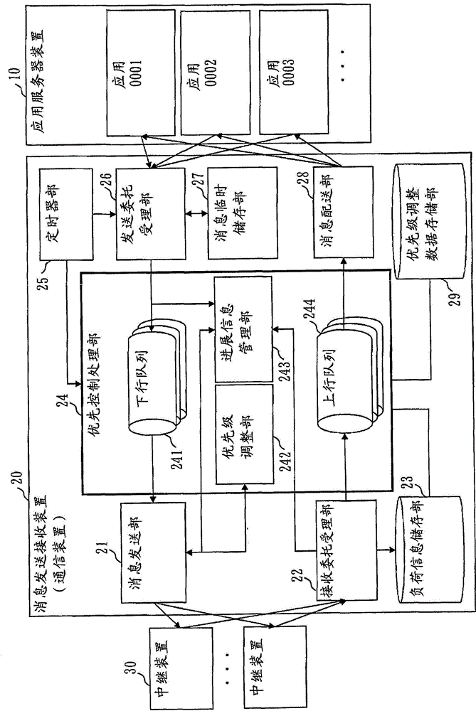
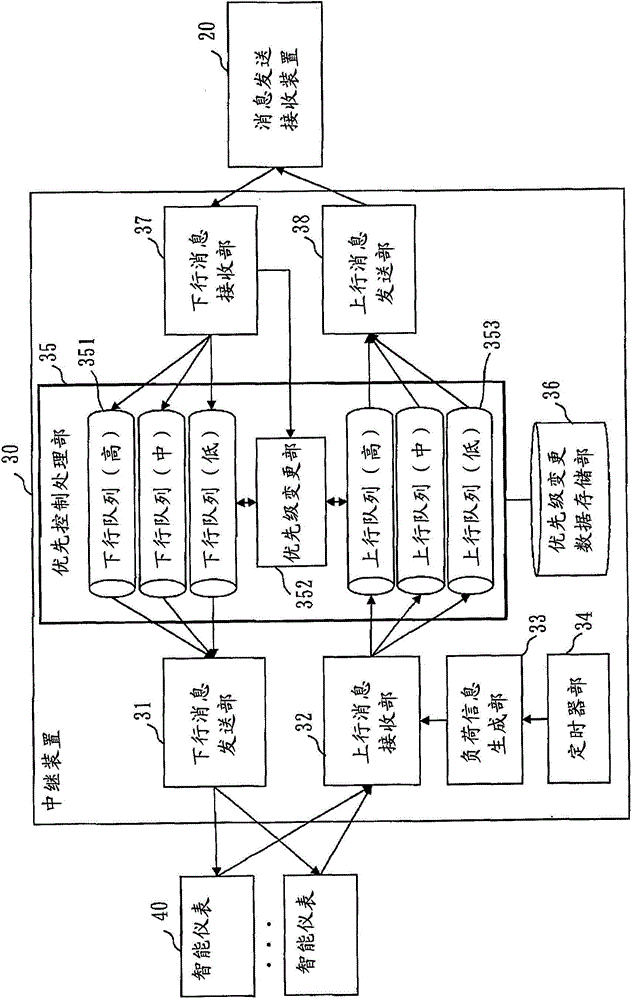
[0378] The configuration of the message transmitting and receiving device 20 of this embodiment is, for example, figure 2 As shown, the structure of the relay device 30 in this embodiment is, for example, image 3 shown.
[0379] In addition, in the present embodiment, in the message transmission/reception device 20 , the priority adjustment unit 242 determines the processing load for processing the downlink message and the uplink message for each relay device 30 .
[0380] Then, the priority adjustment unit 242 determines the transmission order of the priority adjustment messages among the plurality of relay devices 30 so that the priority adjustment messages are transmitted from the relay devices 30 with a high processing load.
[0381] In the present embodiment, the priority adjustment unit 242 also functions as a transmission order determination unit.
[0382] In addition, the message transmission unit 21 transmits the priority adjustment message to the plurality of relay devices 30 according to the transmission order determined by the priority adjustment unit 242 .
[0383] Figure 8 The priority information table when the priority adjustment unit 242 adjusts the order of transmitting priority adjustment messages to the relay device 30 is shown.
[0384] Figure 8 The priority adjustment table is in the Figure 4 In the priority information table of , a column table of the relay device load level is added.
[0385] Columns and Figure 4 The priority information table is the same.
[0386] The relay device load level indicates the load level of the relay device that has transmitted the priority adjustment message, meaning that the larger the value, the higher the load level.
[0387] For example, in a case where the load level of the relay device is "3", it means that a priority adjustment message has been sent to the relay device 30 whose load level is greater than "3".
[0388] "0" (zero) indicates that priority adjustment messages have been sent for all relay devices 30 .
[0389] When the value of the relay device load level in the priority adjustment table is "3", the relay device load table ( Figure 10 ) whose load level is "3", the relay device 30 transmits the priority adjustment message.
[0390] Next, the value of the relay load level of the priority adjustment table is decremented to "2", for the relay load table ( Figure 10 ) whose load level is "2" transmits the priority adjustment message.
[0391] In this way, the value of the relay device load level in the priority adjustment table is decremented, and the priority adjustment messages are transmitted sequentially from the relay device 30 with the higher load level.
[0392] In addition, in the following, for simplicity of description, the value of the load level of the relay device in the priority adjustment table is set to either "1" or "0".
[0393] Therefore, the following relay device specification table ( Figure 9 ) has a load threshold of only 1.
[0394] When the relay device load level of the priority adjustment table is set to, for example, "0", "1", "2", and "3", the relay device specification table ( Figure 9 ) has three steps (a threshold from "0" to "1", a threshold from "1" to "2", and a threshold from "2" to "3").
[0395] The load information storage unit 23 has Figure 10 A relay load table as shown.
[0396] The relay device ID is an ID for uniquely identifying the relay device 30 .
[0397] The relay device model ID is an ID for uniquely identifying the model of the relay device 30 .
[0398] The number of retained messages is the number of messages retained in the upstream queue 353 and downstream queue 351 of the relay device 30 , and represents the load status of the relay device 30 .
[0399] The relay device 30 periodically transmits the number of reserved messages to the message transmitting and receiving device 20 as a load information message.
[0400] The load level is obtained by dividing the load status of the relay device 30 into levels.
[0401] A higher value of the load level indicates a higher load on the relay device 30 .
[0402] In the load level history, when the load level is updated, the load level before the update is described.
[0403] The load information storage unit 23 has Figure 9 Relay device specification table as shown.
[0404] The relay device specification table holds specification information for each model of the relay device 30 used in the smart meter automatic meter look-up system.
[0405] The relay device model ID is an ID for uniquely identifying the model of the relay device 30 .
[0406] The relay device model number is a model number assigned to the relay device 30 .
[0407] The load threshold is a threshold value of the number of reserved messages set for each relay device model, and when the number of reserved messages at a certain point in time exceeds the threshold, it is determined that the load of the relay device 30 is high.
[0408] The processing throughput is the message processing capability of the relay device 30 set for each relay device model.
[0409] When receiving the load information message from the relay device 30, the reception request accepting unit 22 writes the data of the number of reserved messages in the message into the corresponding reserved message of the relay device 30 in the relay device load table of the load information storage unit 23. column of numbers.
[0410] In this embodiment, as an example, when the priority adjustment unit 242 transmits the priority adjustment message to the relay device 30 , it transmits in two stages according to the load status of the relay device 30 .
[0411] Therefore, the load level of the relay device in the priority information table takes a value of "1" or "0" as described above, and when a record for a transmission request is newly created in the priority information table, it is initialized to "0".
[0412] Figure 19 It is a flowchart when the priority adjustment unit 242 adjusts the order of transmitting priority adjustment messages to the relay device 30 .
[0413] The priority adjustment unit 242 is called by a regular timing signal from the timer unit 25 .
[0414] The priority adjustment unit 242 first updates the relay device load table ( Figure 10 ) load level, and load level history information (S31).
[0415] Next, the priority adjustment unit 242 reads the record of the first transmission request ID in the priority information table (S32).
[0416] At this time, when there is no data in the column of the reception deadline time ("No" in S33), the priority adjustment unit 242 judges that the priority does not need to be adjusted, and reads the record of the next transmission request ID (S32 ).
[0417] When there is data in the column of the reception deadline time ("Yes" in S33) and the priority adjustment index is "0" ("0" in S34), the priority adjustment unit 242 executes whether the priority is necessary or not. Adjustment checking process (S35), it is judged whether to adjust the priority.
[0418] Whether the priority needs to be adjusted check processing (S35) and Figure 14 same as the S14, for example, conduct Figure 15 ~ Figure 17 treatment shown.
[0419] When it is determined that the priority needs to be adjusted (YES in S36), the priority adjustment unit 242 writes "+1" in the column of the priority adjustment index of the transmission request ID in the priority information table. , and write "1" in the column of the load level of the relay device (S37).
[0420] Next, the priority adjustment unit 242 executes the priority adjustment message processing (1), and transmits the priority adjustment message to the relay device 30 with a high load (S38).
[0421] On the other hand, when there is data in the column of the reception deadline time ("Yes" in S33), and the priority adjustment index has become "+1" ("+1" in S34), the priority adjustment The unit 242 refers to the relay device load level (S40).
[0422] When the relay device load level is "0" ("0" in S40), it is determined that the priority adjustment message has been sent to all the relay devices 30, and the priority adjustment unit 242 reads the information in the priority information table. Next send the record of the commission ID.
[0423] When the relay device load level is "1", the priority adjustment unit 242 executes the priority adjustment message processing (2) after updating the relay device load level to "0" (S41), and prioritizes messages that have not yet been sent. The relay device 30 of the priority adjustment message transmits the priority adjustment message (S42).
[0424] The priority adjustment unit 242 executes the above processing for all transmission request IDs in the priority information table (S39).
[0425] Figure 20 This is a flowchart of the relay device load table update process ( S31 ) when the priority adjustment unit 242 adjusts the order of transmitting priority adjustment messages to the relay device 30 based on the number of held messages of the relay device 30 .
[0426] The priority adjustment unit 242 first reads the relay device load table ( Figure 10 ) record of the first relay device ID (S3111).
[0427] Next, the priority adjustment unit 242 writes the value of the load level column in the read record into the load level history column of the corresponding record in the relay device load table ( S3112 ).
[0428] Next, the priority adjustment unit 242 uses the value in the relay device model ID column in the read record as a key, and selects the value from the relay device specification table ( Figure 9 ) to read the load threshold of the corresponding relay device model (S3113).
[0429] Next, the priority adjustment unit 242 compares the number of reserved messages in the relay device load table with the load threshold (S3114), and if the number of reserved messages is greater than the load threshold ("Yes" in S3115), the relay device load table "1" is written in the load level column of the corresponding record (S3116).
[0430] On the other hand, when the number of retained messages is not greater than the load threshold ("No" in S3115), "0" (zero) is written in the load level column of the corresponding record in the relay device load table (S3117) .
[0431] The priority adjustment unit 242 executes the above processing for all relay device IDs in the relay device load table (S3118).
[0432] Figure 21 It is the relay device load table update process ( S31) flow chart.
[0433] The priority adjustment unit 242 first reads the relay device load table ( Figure 10 ) record of the first relay device ID (S3121).
[0434] Next, the priority adjustment unit 242 writes the value of the load level column in the read record into the load level history column of the corresponding record in the relay device load table ( S3122 ).
[0435] Next, the priority adjustment unit 242 uses the value in the relay device model ID column in the read record as a key, and reads the processing throughput of the corresponding relay device model from the relay device specification table (S3123).
[0436] Next, the priority adjustment unit 242 calculates the time required for message processing based on the number of messages held in the relay device load table and the processing throughput (S3124).
[0437] When the calculated message processing required time is greater than, for example, a predetermined message processing required time threshold, "1" is written in the load level column of the corresponding record in the relay device load table, and in the further If it is small, "0" (zero) is written (S3125, S3126).
[0438] However, instead of using the predetermined message processing required time, other determination methods such as the following method may be used: for all the relay devices 30 whose message processing required time is larger than half, the load level is arranged in a row It becomes "1", and the load level columns of the remaining relay devices 30 are set to "0".
[0439] Figure 22 Yes Figure 19 A flowchart of the priority adjustment message processing (1) (S38).
[0440] The priority adjustment message process (1) is executed as a process in which the priority adjustment unit 242 adjusts the order in which priority adjustment messages are transmitted to the relay device 30 .
[0441] In the priority adjustment message processing (1), the priority adjustment unit 242 first reads the relay device load table ( Figure 10 ) record of the first relay device ID (S3801).
[0442] When the load level column is "0" ("0" in S3802), the priority adjustment unit 242 determines that the priority adjustment message is not to be transmitted to the corresponding relay device 30, and reads the next record.
[0443] When the load level column is "1" ("1" in S3802), the priority adjustment unit 242 creates a priority adjustment message (S3803), and transfers the created priority adjustment message to the message transmission unit 21 ( S3804).
[0444] The priority adjustment unit 242 executes the above processing for all relay device IDs in the relay device load table (S3805).
[0445] Figure 23 is a flowchart of the priority adjustment message processing (2).
[0446] The priority adjustment message process (2) is executed as a process in which the priority adjustment unit 242 adjusts the order in which the priority adjustment messages are transmitted to the relay device 30 .
[0447] In the priority adjustment message processing (2), the priority adjustment unit 242 first reads the relay device load table ( Figure 10 ) record of the first relay device ID (S4201).
[0448] When the load level history column is "1" ("1" in S4202), the priority adjustment unit 242 determines that a priority adjustment message has been transmitted to the corresponding relay device 30, and reads the next record.
[0449] When the load level history column is "0" ("0" in S4202), a priority adjustment message is created (S4203), and the created priority adjustment message is transferred to the message transmitter 21 (S4204).
[0450] The priority adjustment unit 242 executes the above processing for all relay device IDs in the relay device load table (S4205).
[0451] Next, the operation of the load information generation unit 33 of the relay device 30 will be described.
[0452] The timer unit 34 transmits, to the load information generation unit 33 , a timing signal notifying that it is time to execute the generation process of the load information for each set interval time.
[0453] The load information generation unit 33 receiving the timing signal accumulates the number of messages retained in the upstream queue 353 and the downstream queue 351 at this point in time, and makes a load information message including the data of the accumulation result, and sends the produced load information message It is forwarded to the uplink message receiving unit 32 .
[0454] The uplink message receiving unit 32 inserts the load information message received from the load information generating unit 33 at the end of the uplink queue according to the priority set in the header.
[0455] In this way, in this embodiment, since the message transmitting and receiving device 20 operates by adjusting the order of priority adjustment according to the specifications and load conditions of the relay device 30, even if relay devices 30 with different performances are mixed, In the automatic meter look-up system of smart meters, the priority of message communication can also be effectively controlled.
[0456] Above, in this embodiment, it has been described
[0457] The relay device also has
[0458] a load information transmitting unit that periodically transmits the number of reserved messages as load information of message processing in the relay device to the message transmitting and receiving device,
[0459] The message sending and receiving device also has
[0460] A relay device load information storage unit that stores load information transmitted from a plurality of relay devices.
[0461]In addition, in this embodiment, it is described
[0462] Priority adjustment unit of priority control processing unit of message transmitting and receiving device
[0463] When instructing a relay device to adjust the priority, the relay device instructs the relay device with the largest number of reserved messages in order.
[0464] In this embodiment, it is described
[0465] The relay device load information storage unit of the message transmitting and receiving device further
[0466] Holding the processing throughput as information of the message processing capability for each model of the relay device,
[0467] Priority adjustment unit of priority control processing unit of message transmitting and receiving device
[0468] From the number of reserved messages and the processing throughput of each relay device, the message processing time required to process all the reserved messages is obtained,
[0469] When instructing a relay device to adjust the priority, the relay device instructs in order from a relay device requiring a longer message processing time.
[0470] Finally, refer to Figure 28 Next, an example of the hardware configuration of the message transmitting/receiving device 20 and the relay device 30 shown in Embodiments 1 and 2 will be described.
[0471] The message transmitting and receiving device 20 and the relay device 30 are computers, and each element of the message transmitting and receiving device 20 and the relay device 30 can be realized by a program.
[0472] As hardware configurations of the message transmitting and receiving device 20 and the relay device 30 , an arithmetic device 901 , an external storage device 902 , a main storage device 903 , a communication device 904 , and an input/output device 905 are connected to the bus.
[0473] The computing device 901 is a CPU (Central Processing Unit, central processing unit) that executes programs.
[0474] The external storage device 902 is, for example, a ROM (Read Only Memory), a flash memory, or a hard disk device.
[0475] The main storage device 903 is RAM (Random Access Memory, random access memory).
[0476] "Load information storage unit 23", "priority adjustment data storage unit 29", "priority change data storage unit 36", "downlink queue 241", "uplink queue 244", "downlink queue 351", "uplink queue 353" " is implemented by, for example, the external storage device 902 or the main storage device 903.
[0477] The communication device 904 corresponds to the physical layers of "-transmission unit", "-reception unit", "-reception unit", and "-delivery unit".
[0478] The input/output device 905 is, for example, a mouse, a keyboard, a display device, and the like.
[0479] The program is usually stored in the external storage device 902 , loaded into the main storage device 903 , and sequentially read into the computing device 901 to be executed.
[0480] The program is implemented as described in figure 1 The program of the function of the "~ part (except for the "load information storage part 23", the "priority adjustment data storage part 29", and the "priority change data storage part 36" is the same below)" is the program of the function.
[0481] Furthermore, an operating system (OS) is stored in the external storage device 902, at least a part of the OS is loaded into the main storage device 903, and the computing device 901 executes the OS while executing the OS. figure 1 The program of the function of the "~ department" shown.
[0482] In addition, in the description of Embodiments 1 and 2, the expressions will be described as "judgment of ~", "judgment of ~", "extraction of ~", "selection of ~", "setting of ~", "designation of ~ ", "update of ~", "production of ~", "generation of ~", "decision of ~", "input of ~", "output of ~", "reception of ~", "send of ~", etc. Information, data, signal values, and variable values resulting from the processing are stored in the main storage device 903 as files.
[0483] In addition, encryption keys/decryption keys, random numbers, and parameters may be stored in the main storage device 903 as files.
[0484] in addition, Figure 28 The structure of the message sending and receiving device 20 and an example of the hardware structure of the relay device 30, the hardware structure of the message sending and receiving device 20 and the relay device 30 is not limited to Figure 28 The described structures may also be other structures.
[0485] In addition, the application server device 10 shown in Embodiments 1 and 2 may be Figure 28 The hardware structure can also be other hardware structures.
[0486] In addition, the processing procedure of the message transmission/reception apparatus 20 and the relay apparatus 30 shown in Embodiment 1 and 2 can be understood as an information processing method.
[0487] In addition, in Embodiments 1 and 2, the message sending and receiving device 20 and the relay device 30 used in the smart meter automatic meter inspection system are described, but the content shown in this embodiment can also be applied to the smart meter automatic meter inspection system. Communication systems other than look-up meter systems.
PUM


Description & Claims & Application Information
We can also present the details of the Description, Claims and Application information to help users get a comprehensive understanding of the technical details of the patent, such as background art, summary of invention, brief description of drawings, description of embodiments, and other original content. On the other hand, users can also determine the specific scope of protection of the technology through the list of claims; as well as understand the changes in the life cycle of the technology with the presentation of the patent timeline. Login to view more.