A method, device and system for automatically adjusting the angle of a probe emission line during puncture

A technology of firing angle and angle, which is applied in the fields of puncture needles, diagnostic probe accessories, medical science, etc., can solve the problems of manual adjustment, difficult to determine the deflection angle, manual adjustment of the firing line and puncture needle, etc., to enhance the accuracy, improve the Imaging efficiency and the effect of improving scanning efficiency

Active Publication Date: 2017-07-04
SONOSCAPE MEDICAL CORP
View PDF3 Cites 0 Cited by
  • Summary
  • Abstract
  • Description
  • Claims
  • Application Information

AI Technical Summary

Problems solved by technology

[0002] In the existing field of puncture ultrasound imaging using a linear array probe, in order to obtain a puncture image that can clearly display the puncture needle, it is necessary to make the emission line of the probe perpendicular to the angle of the puncture needle. However, in the actual operation process, since the linear array probe is usually not When operating with the puncture frame, the angle between the emission line and the puncture needle often needs to be adjusted manually
[0003] The disadvantage of the prior art is that the deflection angle is not easy to determine without using the puncture frame because the emission angle of the emission line often needs to be manually adjusted during the adjustment process.

Method used


Image

  • A method, device and system for automatically adjusting the angle of a probe emission line during puncture
  • A method, device and system for automatically adjusting the angle of a probe emission line during puncture
  • A method, device and system for automatically adjusting the angle of a probe emission line during puncture

Examples


Embodiment 1

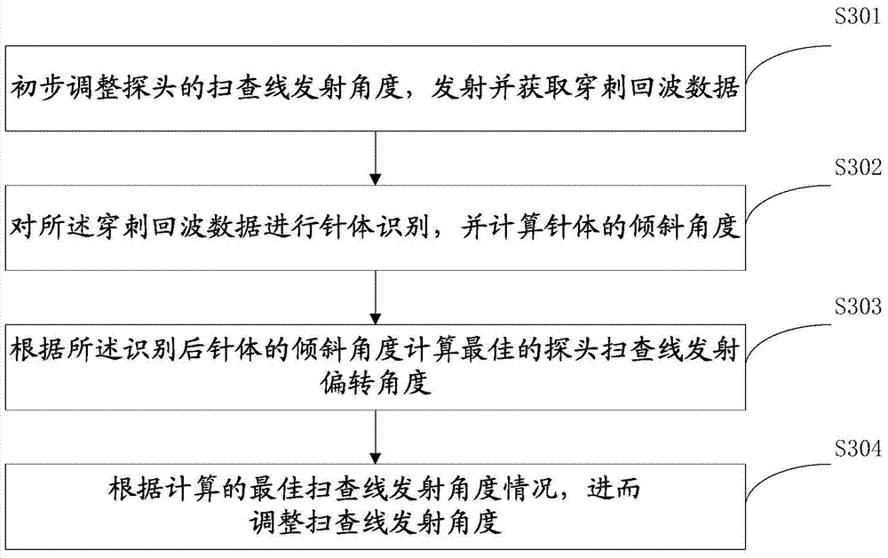
[0031] Such as figure 1 As shown, the method for automatically adjusting the angle of the probe emission line in the puncture includes the following steps:

[0032] S101, preliminarily adjusting the scanning line emission angle of the probe, emitting and acquiring puncture echo data.

[0033] By manually adjusting the deflection angle of the scanning line of the probe, the preliminary puncture echo data can be obtained. Theoretically, when the scanning line emission angle of the probe is at an optimized angle perpendicular to or close to the perpendicular (between 85-95 degrees) to the puncture needle, the display of the puncture needle is most obvious.

[0034] When using a linear array probe for scanning, usually the puncture needle and the linear array probe are not used in conjunction with the puncture frame, and manual adjustment is required. Usually, it is difficult to accurately obtain the required optimal angle through manual adjustment. Therefore, the display of the...

Embodiment 2

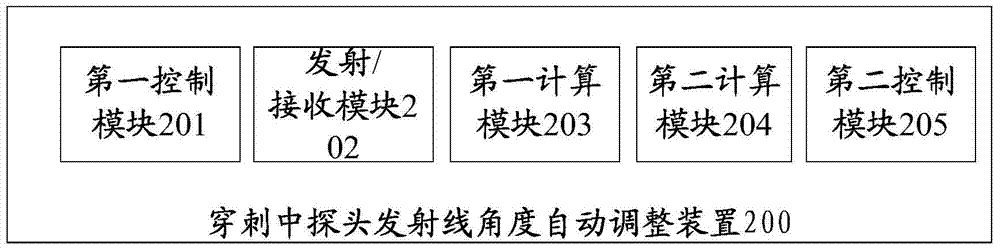
[0076] Such as image 3 As shown, the present invention also provides a puncture needle display device, which includes: a first control module 201 , a transmitting / receiving module 202 , a first calculation module 203 , a second calculation module 204 , and a second control module 205 .

[0077] The first control module 201 is used to preliminarily adjust the scanning line emission angle of the probe;

[0078] A transmitting / receiving module 202, configured to transmit and acquire puncture echo data;

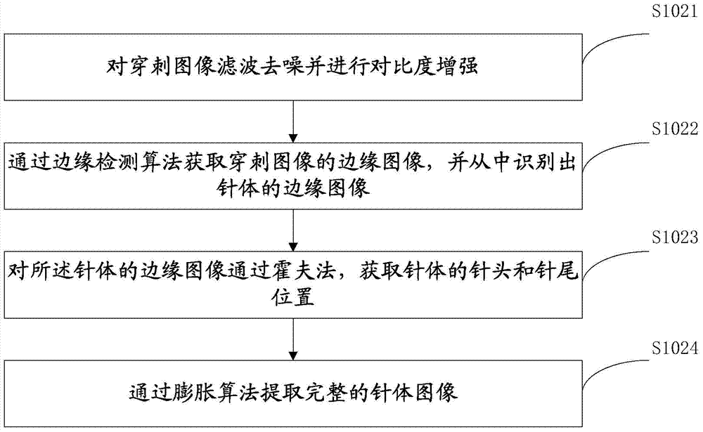
[0079] The first computing module 203 is configured to perform needle body recognition on the puncture image echo data, and calculate the inclination angle of the needle body; specifically, it includes the following:

[0080] Used to filter and denoise the puncture image and perform contrast enhancement;

[0081] It is used to obtain the edge image of the puncture image through the edge detection algorithm, and identify the edge image of the needle body therefrom;

[0082] It...

Embodiment 3

[0090] The present invention also provides a system, the system has the device as described in the second embodiment, the device and the working process of the device are detailed in the first and second embodiments and will not be repeated here.


PUM


Abstract

The invention provides an automatic adjusting method for an emission line angle of a puncture needle probe. The method comprises the following steps: primarily adjusting a scanning line emission angle of the probe; emitting and obtaining puncture echo data; carrying out needle body identification on the puncture echo data, and calculating an inclined angle of a needle body; calculating an optimal scanning line emission angle of the probe according to the inclined angle of the identified needle body; and adjusting the scanning line emission angle according to the calculated optimal scanning line emission angle condition. The invention further provides corresponding device and system. By the aid of the method, the scanning line emission angle can be automatically adjusted according to the position of a puncture needle.

Description

technical field [0001] The invention relates to the technical field of puncture ultrasound images, in particular to a method, device and system for automatically adjusting the angle of a probe emission line during puncture. Background technique [0002] In the existing field of puncture ultrasound imaging using a linear array probe, in order to obtain a puncture image that can clearly display the puncture needle, it is necessary to make the emission line of the probe perpendicular to the angle of the puncture needle. However, in the actual operation process, since the linear array probe is usually not When operating with the puncture frame, the angle between the emission line and the puncture needle often needs to be manually adjusted. [0003] The disadvantage of the prior art is that it is not easy to determine the deflection angle without using a puncture frame because the emission angle of the emission line often needs to be adjusted manually during the adjustment proces...

Claims


Application Information

Patent Timeline
Patent Type & Authority Patents(China)
IPC IPC(8): A61B17/34A61B8/00
CPCA61B8/0841A61B8/42A61B17/3403A61B2017/3413
Inventor 杨仲汉冯乃章梁丁
Owner SONOSCAPE MEDICAL CORP
Why Eureka
Try Eureka