A kind of packaging machinery lane change switching device

A switching device and packaging machinery technology, applied in the direction of transportation and packaging, conveyor objects, etc., can solve the time-consuming and labor-intensive problems, and achieve the effect of convenient lane change, reasonable design, and simple structure

Active Publication Date: 2016-07-06
JOYEA CORP
View PDF6 Cites 0 Cited by
  • Summary
  • Abstract
  • Description
  • Claims
  • Application Information

AI Technical Summary

Problems solved by technology

[0002] On the material packaging line, according to the packaging variety and packaging specifications, the materials are sorted by the packaging machinery, and the number of channels and channel references for material transportation are often changed according to the process requirements. For the above-mentioned changes, the existing technology replaces the packaging machinery as a whole Not only do you need to store multiple sets of different channel parts, but it is also very time-consuming and laborious to replace the channel parts.

Method used


Image

  • A kind of packaging machinery lane change switching device
  • A kind of packaging machinery lane change switching device
  • A kind of packaging machinery lane change switching device

Examples


Embodiment 1

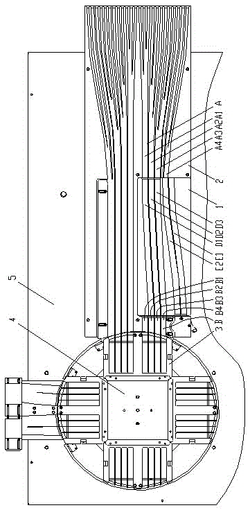
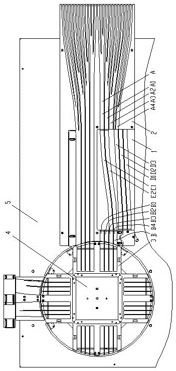
[0025] Such as figure 1 , figure 2 or image 3 As shown, the lane-changing switching device for packaging machinery of the present invention includes a bottom plate 5 , a front channel plate 2 , a rear channel plate 3 and a switching plate 1 . The front passage plate 2 is provided with a front passage A, and the front passage A includes an inner reference passage and an ordinary passage. In this embodiment, the front passage A includes four U-shaped (section) material passages: front passage IA1, The front channel ⅡA2, the front channel ⅢA3 and the front channel IVA4, that is, the number of material channels in the front channel A is 4, and the specifications (width and height) of the four material channels in the front channel A are the same, and the distance between the channels (the distance between the center lines) Similarly, the innermost channel of the front channel A, in this embodiment, the front channel IA1, is set as the inner reference channel; the rear channel ...

Embodiment 2

[0043] This embodiment is basically similar to Embodiment 1, the difference is that in this embodiment, the number of material passages in the front passage A is 2-10, and the number of material passages in the rear passage B is 2-10, that is, the front passage A and the rear channel, each including at least 3 material channels, each including a maximum of 10 material channels; the number of material channels for the switching channel is 1-10, that is, the switching channels include at least 1 material channel, and each includes 10 at most. Material channel. When the number of material channels of the switching channel is 1, the channel is used as both the inner channel and the outer channel, and the entrance and exit of the channel are respectively aligned with the inner reference channel and the outer reference channel.


PUM


Abstract

The invention discloses a channel switching device for packaging machinery and belongs to the technical field of packaging machinery. The lane switching device comprises a base board (5), a front channel plate (2), a rear channel plate (3) and a switching board (1). The front channel plate (2) is equipped with a front channel (A). The front channel (A) comprises an inner baseline channel and a common channel. The rear channel plate (3) is equipped with a rear channel (B). The rear channel (B) comprises an outer baseline channel and a common channel. The switching board (1) is equipped with a switching channel. The switching channel comprises an inner channel, an outer channel and a common channel. The channel switching device for packaging machinery is reasonable in design and simple in structure. In the process of production, the switching channel of the channel switching device for packaging machinery is very convenient. The whole material channels are unnecessary to be changed completely, and only need to switch the switching board simply. The switching can be realized conveniently. The time and labor are saved, and the working efficiency is very high.

Description

technical field [0001] The invention relates to the technical field of packaging machinery, in particular to a lane-changing switching device for the packaging machinery. Background technique [0002] On the material packaging line, according to the packaging variety and packaging specifications, the materials are sorted by the packaging machinery, and the number of channels and channel references for material transportation are often changed according to the process requirements. For the above-mentioned changes, the existing technology replaces the packaging machinery as a whole Not only do multiple sets of different channel parts need to be stored, but it is also very time-consuming and labor-intensive to replace the channel parts. Contents of the invention [0003] In view of the above-mentioned problems in the production of packaging machinery, the purpose of the present invention is to provide a switching device for changing lanes of packaging machinery, which uses ma...

Claims


Application Information

Patent Timeline
Patent Type & Authority Patents(China)
IPC IPC(8): B65G47/52
Inventor 殷祥根张小平
Owner JOYEA CORP
Why Eureka
Try Eureka