Railway tunnel outlet clapboard type buffering structure

A buffer structure and baffle-type technology, applied in tunnels, mining equipment, earth-moving drilling, etc., can solve the problems of difficult tunnel opening buffer structure reconstruction, inability to build a structural buffer structure, and uneconomical problems, so as to alleviate the micro-pressure wave at the opening. effect, maximizing economic benefits, reducing the effect of stress peaks

Active Publication Date: 2015-04-08
CHINA RAILWAY SIYUAN SURVEY & DESIGN GRP
View PDF6 Cites 0 Cited by
  • Summary
  • Abstract
  • Description
  • Claims
  • Application Information

AI Technical Summary

Problems solved by technology

[0005] 1) In actual construction, sometimes limited by the local terrain, it is impossible to build a buffer structure with a complex structure, which cannot meet the micro pressure wave control standard
[0006] 2) Some of the existing buffer structures at tunnel entrances are expensive, complex in structure, difficult to implement, and not economical enough
[0007] 3) It is not easy to modify the buffer structure of the existing tunnel entrance, and the modification cost is high

Method used


Image

  • Railway tunnel outlet clapboard type buffering structure
  • Railway tunnel outlet clapboard type buffering structure
  • Railway tunnel outlet clapboard type buffering structure

Examples


Embodiment Construction

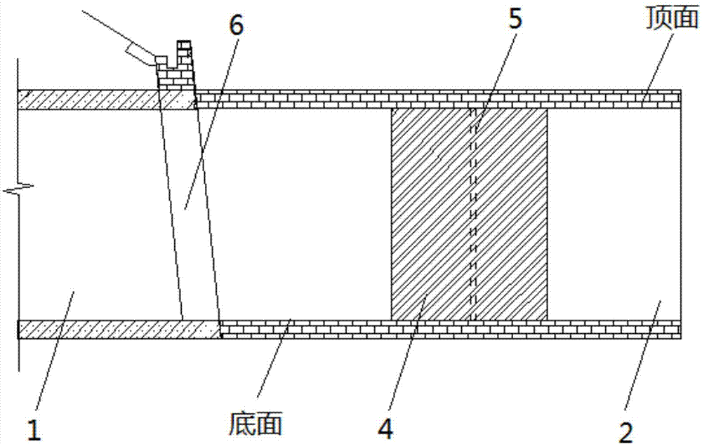
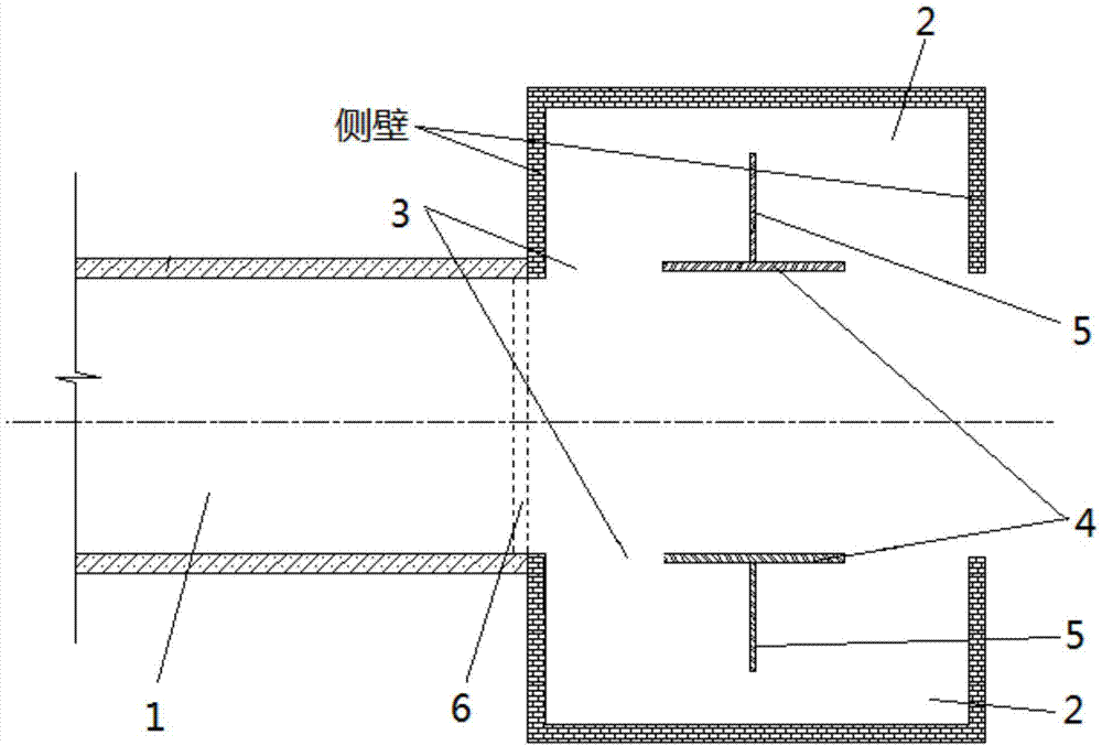
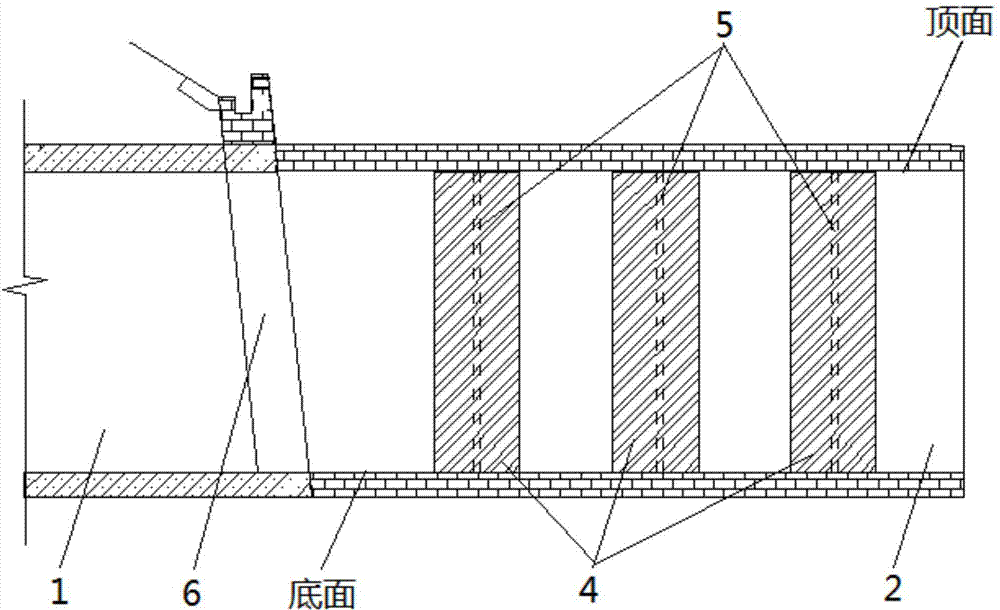
[0026] Such as figure 1 and figure 2 As shown, the railway tunnel exit partition plate type buffer structure designed by the present invention has a type box 2 respectively arranged on both sides of the tunnel exit 6, and the side wall of the type box 2 close to the center line of the tunnel 1 is an opening surface 3; The box 2 is provided with a first partition 4 parallel to the opening surface 3, and the two ends of the first partition 4 are fixedly connected to the top surface and the bottom surface of the mold box 2, and the same mold box 2 The sum of the areas of the first partition 4 is less than the area of ​​the opening surface 3 of the mold box 2; and the second partition 5 connected with the first partition 4, the second partition 5 stretches into the mold box 2 . The area mentioned here means that the first separator 4 is regarded as a surface with a thickness of 0, just like the opening surface 3 . Preferably, the area of ​​the first partition 4 at the same mol...


PUM


Abstract

The invention discloses a railway tunnel outlet clapboard type buffering structure. A mold box is arranged on each of the two sides of a tunnel outlet; the side wall, close to the middle line of a tunnel, of each mold box is an opening surface; at least one first clapboard parallel to the opening surface is arranged at each mold box; the two ends of each first clapboard are fixedly connected with the top surface and the bottom surface of the corresponding mold box; the sum of the area of the first clapboards at the same mold box is smaller than the area of the opening surface of the mold box; second clapboards are connected with the first clapboards and extend into the mold boxes. Due to the fact that the mold boxes are arranged at the tunnel outlet and the clapboards are arranged at the mold boxes, the defect of tunnel outlet micropressure wave effect due to disability of building a complex buffering structure because of the restraint of landform is relieved, the clapboards can distribute compression wave, the propagation energy of the compression wave is separated, the pressure peak of the micropressure wave is reduced, the micropressure wave effect at the outlet can be obviously relieved, under the condition of the same construction cost, the pressure peak of the micropressure wave at the outlet is greatly reduced, economic benefit is maximized, and the structure has relatively high practicability.

Description

technical field [0001] The invention relates to a railway tunnel, in particular to an in-cavity buffer structure for high-speed railways, intercity railways and urban railway tunnels. Background technique [0002] When the train enters the tunnel from the exposed line outside the tunnel at a relatively high speed, the air in front of the train cannot diffuse to the surroundings in time due to the sudden restriction of the space around the train, and the air compression wave is formed in front of the train. The compression wave travels to the tunnel exit at the speed of sound, about 90% of it is reflected back to the tunnel entrance in the form of expansion waves, and the other 10% of the energy is radiated from the tunnel exit to the surrounding area in the form of pulse-like shock waves, forming micro-pressure Wave. If the micro-pressure wave effect is too strong, it will produce aerodynamic blasting noise, that is, tunnel sonic boom, and cause problems such as rapid vibra...

Claims


Application Information

Patent Timeline
Patent Type & Authority Applications(China)
IPC IPC(8): E21D9/14
CPCE21D9/14
Inventor 赵文成徐向东肖明清
Owner CHINA RAILWAY SIYUAN SURVEY & DESIGN GRP
Why Eureka
Try Eureka