Eureka AIR delivers breakthrough ideas for toughest innovation challenges, trusted by R&D personnel around the world.

High-speed railway tunnel structure

A tunnel structure, high-speed railway technology, applied in tunnels, mining equipment, earthwork drilling and mining, etc., can solve the micro-pressure wave effect at the entrance of the tunnel, the air resistance of the aerodynamic load locomotive, the inability to comprehensively alleviate the aerodynamic effect, and the inability to open the tunnel Set buffer structure and other issues to achieve the effects of alleviating the micro-pressure wave effect at the opening, alleviating the aerodynamic effect, and alleviating the negative pressure

Inactive Publication Date: 2014-07-09
CHINA RAILWAY SIYUAN SURVEY & DESIGN GRP
View PDF0 Cites 4 Cited by
  • Summary
  • Abstract
  • Description
  • Claims
  • Application Information

AI Technical Summary

Problems solved by technology

Improving the airtight performance of the locomotive can effectively reduce the transient pressure inside the locomotive and improve the comfort of passengers, but it cannot solve the problems of micro-pressure wave effect at the opening, aerodynamic load, and additional air resistance of the locomotive
[0004] The various existing measures to alleviate the aerodynamic effect of high-speed railway tunnels are relatively simple. Sometimes due to the limitation of the topography of the tunnel entrance, it is impossible to install a buffer structure at the tunnel entrance, nor can it play a role in comprehensively mitigating the aerodynamic effect.

Method used


Image

  • High-speed railway tunnel structure
  • High-speed railway tunnel structure

Examples


Embodiment Construction

[0015] Further illustrate the present invention below in conjunction with accompanying drawing:

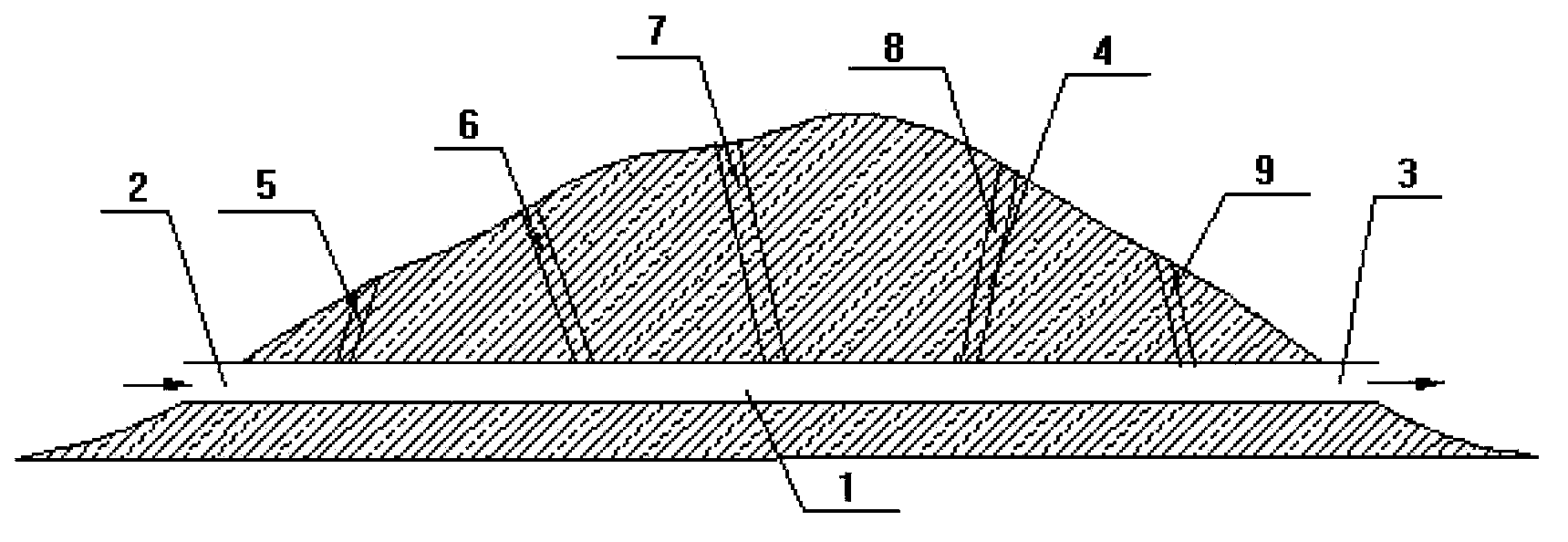
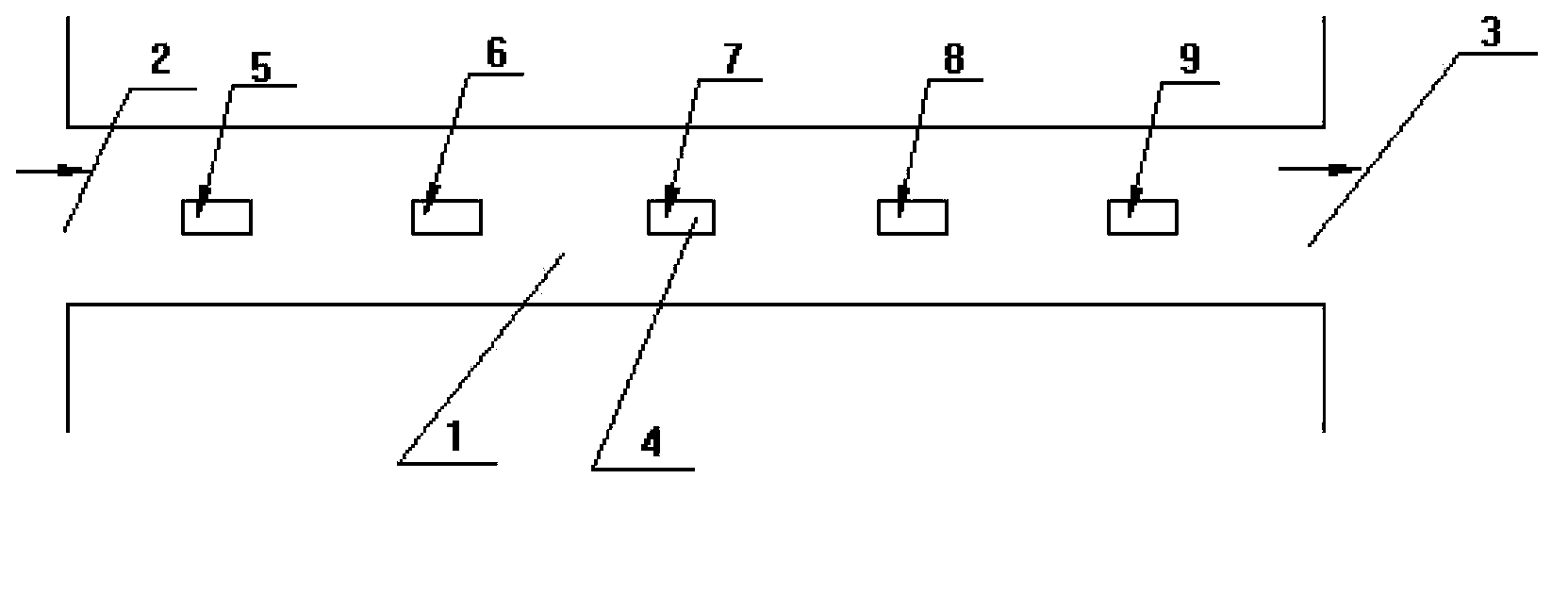
[0016] Such as figure 1 As shown, in the high-speed railway tunnel structure of the present invention, openings 4 are arranged on the top of the lining of the tunnel 1, and the openings 4 are five evenly arranged, the first opening 5, the second opening 6, the third opening 7, the fourth opening 8, Fifth opening9. The distance between the first opening 5 and the tunnel entrance opening 2 and the distance between the fifth opening 9 and the tunnel exit opening 3 is 20-50m. In order to effectively reduce the peak value of the micro-pressure wave at the entrance, the transient pressure in the locomotive, the additional air resistance of the locomotive, and the aerodynamic load in the tunnel. The opening 4 at the top of the tunnel 1 is realized by a horizontal shaft or an inclined shaft.

[0017] Such as figure 2 As shown, in the high-speed railway tunnel structure of the present...


PUM


Abstract

The invention provides a high-speed railway tunnel structure. The high-speed railway tunnel structure is characterized in that both side surfaces or the top of a tunnel lining is provided with openings which are communicated with the atmosphere, 3-5 openings are distributed in the full length direction of the tunnel, the neighboring openings are spaced at equal intervals, and the opening close to the portal of the tunnel is 20-50 m away from the portal. According to the high-speed railway tunnel structure, 3-5 the openings are arranged on the side walls or the top of the tunnel lining, so that the transient pressure inside a locomotive and the micropressure peak value of the portal can be reduced, the micropressure wave effects of the portal can be released, and the locomotive additional air resistance of a long tunnel can be reduced obviously; meanwhile, the energy of expansion waves reflected back to the tunnel from the exit of the tunnel can be reduced, further the negative pressure inside opencuts and on the outer wall of the locomotive can be effectively released, and the fatigue damage of the opencut structure and auxiliary facilities due to aerodynamic load can be reduced. Besides, the high-speed railway tunnel structure is restricted little by surrounding terrains and has high adaptability, and meanwhile, is low in construction cost and highly practical.

Description

technical field [0001] The invention relates to the field of high-speed railway tunnels, in particular to a high-speed railway tunnel structure. Background technique [0002] When a high-speed train passes through a tunnel, a series of aerodynamic effects will occur, including: the pressure in the tunnel suddenly rises, causing a transient pressure in the locomotive, and the transient pressure will generate a pressure difference in the eardrum of the human body, causing the passenger's eardrum Discomfort, even dizziness and vomiting, seriously affect the comfort and health of passengers. Pneumatic blasting noise, train window vibration, and rapid vibration of nearby light structures (house doors and windows) and other micro-pressure wave phenomena occur at the exit of the tunnel, resulting in serious noise pollution and seriously affecting the environment around the exit of the tunnel and the daily life of residents. The locomotive, tunnel lining structure and auxiliary fac...

Claims


Application Information

Patent Timeline
Patent Type & Authority Applications(China)
IPC IPC(8): E21D9/14
Inventor 赵文成徐向东肖明清王克金龚彦峰王长法李鸣冲李文胜廖斌靳宗振
Owner CHINA RAILWAY SIYUAN SURVEY & DESIGN GRP
Why Eureka
Eureka Blog
Learn More