Catenary geometric parameter measurement and calibration method suitable for high-speed trains
A high-speed motor train, geometric parameter technology, applied in measurement devices, optical devices, instruments, etc., can solve the problems of low measurement accuracy, inaccurate measurement results, and the camera target surface and the bow lifting plane are not parallel, so as to eliminate image distortion. , the effect of accurate measurement results
- Summary
- Abstract
- Description
- Claims
- Application Information
AI Technical Summary
Problems solved by technology
Method used
Image
Examples
Embodiment 1
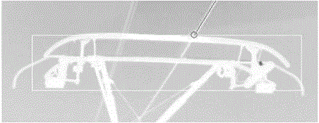
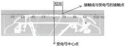
[0039] Such as Figure 1-5 Shown, the present invention comprises the steps:
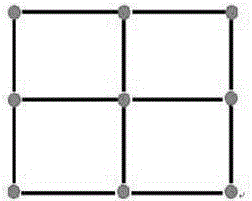
[0040] A1 Prepare a 9-point calibration board: use aluminum alloy profiles to customize the calibration board, set nine high-temperature hot spots of cement resistors at equal intervals on the surface of the calibration board, and set nylon clips between the bottom of each cement resistor and the calibration board to prevent cement The heat generated by the resistance is transmitted to the calibration board, which affects the thermal imaging accuracy. The manufacturing and assembly accuracy of the 9-point calibration board is controlled below 1mm. In addition, set the actual coordinates (u, v, w) of nine cement resistance high temperature hot spots, where w is a constant. Such as Figure 5 As shown, the method of setting u and v in the 9 real coordinates is as follows: Assume that point 1 in the figure is (0, 0), the actual distance between point 1 and point 2 is △x, and the actual distance betwee...
Embodiment 2
[0047] This scheme is preferably as follows on the basis of Example 1: the calibration requirement in step a2 is that the height of the three cement resistance high-temperature hot spots on the calibration board is at 6300 ± 1 mm on the track plane, and the three cement resistance high-temperature hot spots in the middle row are at 5800 ± 1 mm. 1mm, the bottom row of cement resistance high temperature hot spot is at 5300±1mm. The 9-point calibration plate can better reflect the situation of the points on the pantograph lifting plane, so that the distortion coefficient calculated based on the 9-point calibration plate is more accurate, and the later calculated conduction height and pull-out value are also more accurate.
Embodiment 3
[0049] The scheme is preferably as follows on the basis of the foregoing embodiments: the specific method for correcting the pixel coordinates (x', y', w') of the infrared camera imaging in step a4 is as follows:
[0050] a41 Calculation of mapping coefficients: According to the relatively fixed pantograph lifting plane and camera target plane, the pixel coordinates (x', y', w') of the infrared camera imaging and the actual coordinates of the pantograph lifting plane (u, v, w) There is a mapping relationship that satisfies the following formula:
[0051]
[0052] In formula (1), due to the need to measure the conductance value and pull-out value of the contact point between the pantograph and the contact line, the contact point only moves in the horizontal and vertical directions perpendicular to the moving direction of the motor vehicle, so the actual The w in the coordinates is a constant, so when calibrating, you only need to calibrate the relative values of these two ...
PUM
 Abstract
Description
Claims
Application Information
 - R&D
- Intellectual Property
- Life Sciences
- Materials
- Tech Scout
- Unparalleled Data Quality
- Higher Quality Content
- 60% Fewer Hallucinations
Browse by: Latest US Patents, China's latest patents, Technical Efficacy Thesaurus, Application Domain, Technology Topic, Popular Technical Reports.
© 2025 PatSnap. All rights reserved.Legal|Privacy policy|Modern Slavery Act Transparency Statement|Sitemap|About US| Contact US: help@patsnap.com


