
Photoelastic modulation measurement system

A measurement system and photoelastic modulation technology, applied in the field of optics, can solve the problems of deviation and limitation in the modulation of photoelastic modulators

Inactive Publication Date: 2015-04-08
INST OF SEMICONDUCTORS - CHINESE ACAD OF SCI
View PDF8 Cites 5 Cited by
  • Summary
  • Abstract
  • Description
  • Claims
  • Application Information

AI Technical Summary

Problems solved by technology

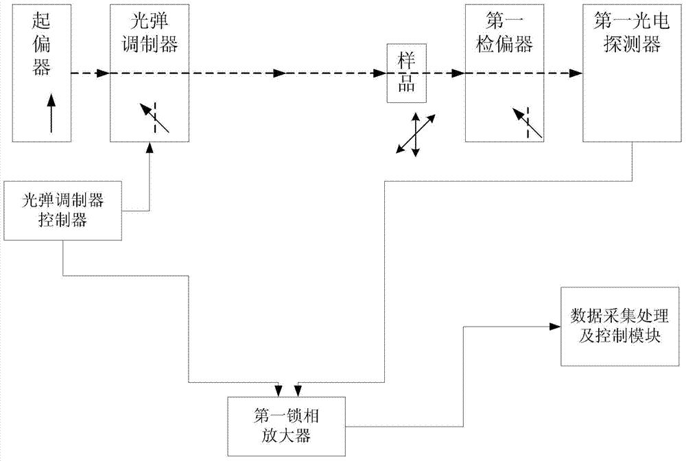
However, due to factors such as its inevitable mechanical vibration and static electricity accumulation, there is a deviation in the modulation of the polarization state of the incident light by the photoelastic modulator, which will be directly reflected in the measurement data, and the data with a high signal / noise ratio can only maintain 2 to 3 minutes, so that the overall experimental precision is limited to 10 -3 magnitude

Method used


Image

  • Photoelastic modulation measurement system
  • Photoelastic modulation measurement system

Examples


Embodiment Construction

[0013] In order to make the object, technical solution and advantages of the present invention clearer, the present invention will be described in further detail below in conjunction with specific embodiments and with reference to the accompanying drawings. It should be noted that, in the drawings or descriptions of the specification, similar or identical parts all use the same figure numbers. Implementations not shown or described in the accompanying drawings are forms known to those of ordinary skill in the art. Additionally, while illustrations of parameters including particular values ​​may be provided herein, it should be understood that the parameters need not be exactly equal to the corresponding values, but rather may approximate the corresponding values ​​within acceptable error margins or design constraints. The directional terms mentioned in the embodiments, such as "upper", "lower", "front", "rear", "left", "right", etc., are only referring to the directions of the...


PUM


Abstract

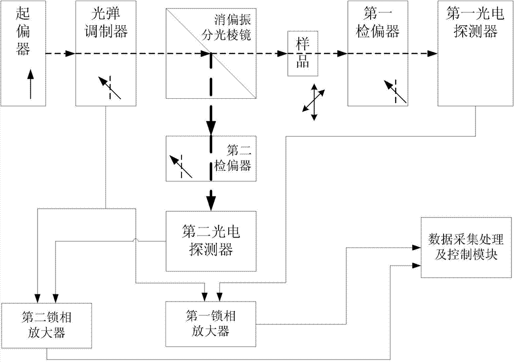
The invention provides a photoelastic modulation measurement system. A reference signal is introduced into the photoelastic modulation measurement system; the reference signal contains information of demodulation deviation of a photoelastic modulator on a polarization state; and data noise caused by the deviation of a modulation state of the photoelastic modulator is curbed through the reference signal.

Description

technical field [0001] The invention relates to the field of optical technology, in particular to a photoelastic modulation measurement system. Background technique [0002] Most crystalline materials respond differently to light of different polarization states, which is one of their important properties. Common polarized optical phenomena include linear polarization dichroism, circular polarization dichroism, linear birefringence, optical rotation, etc. These properties can be conveniently measured with photoelastic modulators combined with other polarizing elements. [0003] figure 1 It is a structural schematic diagram of a photoelastic modulation measurement system in the prior art. Such as figure 1 As shown, the polarizer generates polarized light with a fixed polarization direction. Under the action of the photoelastic modulator, the photoelastic effect of the window crystal produces high-speed polarization state modulation on the beam passing through it. The modu...

Claims


Application Information

Patent Timeline
IPC IPC(8): G01N21/21
Inventor 张宏毅陈涌海高寒松
Owner INST OF SEMICONDUCTORS - CHINESE ACAD OF SCI
Learn More