Light complementary splicing technology for generating space gradual transition view and three-dimensional display system based on light complementary splicing technology

A technology for generating space and views, applied in optics, optical components, instruments, etc., can solve problems such as affecting display quality, achieve continuous motion parallax, and improve display effects.

Active Publication Date: 2015-04-08
SUN YAT SEN UNIV
View PDF4 Cites 8 Cited by
  • Summary
  • Abstract
  • Description
  • Claims
  • Application Information

AI Technical Summary

Problems solved by technology

However, the transition between adjacent views often occurs suddenly. When the spacing or angular spacing of the sub-display areas is not very small, a three-dimensional effect of "jumping" transition will be generated between adjacent display views, which will affect the display quality.

Method used


Image

  • Light complementary splicing technology for generating space gradual transition view and three-dimensional display system based on light complementary splicing technology
  • Light complementary splicing technology for generating space gradual transition view and three-dimensional display system based on light complementary splicing technology
  • Light complementary splicing technology for generating space gradual transition view and three-dimensional display system based on light complementary splicing technology

Examples


Embodiment 1

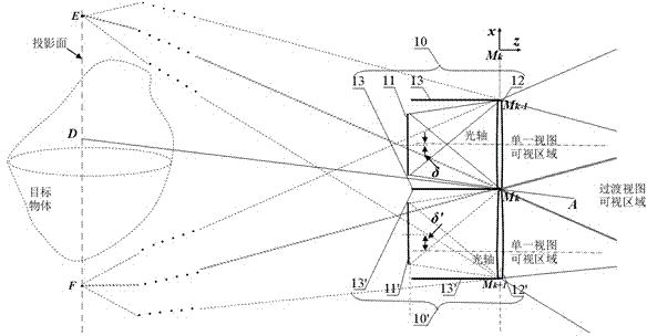
[0049] A three-dimensional display system constructed according to type I steps adopts type I limited projection units 10 in a linear arrangement (the distance between the display device 11 and the projection lens 10 is smaller than the focal length of the projection lens 10). Such as figure 1 As shown, two constrained projection units 10 and 10 ′ arranged along a one-dimensional linear direction are taken as an example for illustration. The limited projection unit 10 includes: a projection device 11 , a projection lens 12 , and a light blocking plate 13 . The limited projection unit 10' includes: a projection device 11', a projection lens 12', and a light blocking plate 13'. The two restricted projection units 10 and 10' are arranged parallel and adjacent to each other along the x direction. When the thickness of the light barrier is relatively small, it can be considered that the projection lenses 12 and 12' share a side point M k ,Pass M k The dot light barriers 13 an...

Embodiment 2

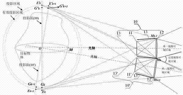
[0054] A three-dimensional display system built according to Type I steps adopts Type I limited projection units 10 arranged in a circular manner (the distance between the display device 11 and the projection lens 10 is smaller than the focal length of the projection lens 10). Such as figure 2 As shown, here we take two constrained projection units 10 and 10 ′ arranged along a one-dimensional circumferential direction as an example for illustration. The limited projection unit 10 includes: a projection device 11 , a projection lens 12 , and a light blocking plate 13 . The limited projection unit 10' includes: a projection device 11', a projection lens 12', and a light blocking plate 13'. The two restricted projection units 10 and 10' are surrounded by O The circle with the point as the center is arranged adjacent to each other, and their relative deflection angle is θ . When the thickness of the baffle is relatively small, it can be considered that the projection lenses ...

Embodiment 3

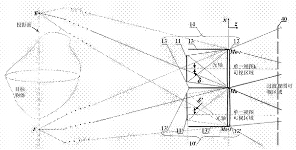
[0059] The three-dimensional display system is built according to the steps of type III by adopting the type I limited projection unit 10 arranged in a straight line (the distance between the display device 11 and the projection lens 10 is smaller than the focal length of the projection lens 10 ). Such as image 3 As shown, two constrained projection units 10 and 10 ′ arranged along a one-dimensional linear direction are taken as an example for illustration. The limited projection unit 10 includes: a projection device 11 , a projection lens 12 , and a light blocking plate 13 . The limited projection unit 10' includes: a projection device 11', a projection lens 12', and a light blocking plate 13'. The two restricted projection units 10 and 10' are arranged parallel and adjacent to each other along the x direction. When the thickness of the light barrier is relatively small, it can be considered that the projection lenses 12 and 12' share a side point M k ,Pass M k The dot ...


PUM


Abstract

The invention discloses a light complementary splicing technology for generating a space gradual transition view and a three-dimensional display system based on the Light complementary splicing technology. On the basis of a display element with large divergence angle display pixels, the light complementary splicing technology and the display system thereof can present a transition view with gradually changed content to a moving view point. The invention provides and designs limited projection units. Each limited projection unit is composed of the display element, a projection lens and a light barrier; through the array structure design for a plurality of projecting units, an auxiliary lens can be selectively combined for coinciding the images, as parallax images, projected by all the limited projection units in a three-dimensional image display area; through the controllable gating of the light barrier for the light emitted from the display element, a field lens is selectively combined for generating a transition view observing area in a view area; the display information received by each space view point in the transition view observing area comes from different space parts of two or more adjacent display elements; the information is end-to-end connected in the space and is spliced into a transition view; the image content of the transition view is changed following the change of the position of the space view point, so that the transition view with gradually changed content is received by the moving view point and the continuous motion parallax presentation is realized; after controllable diaphragms are arranged in the view area or arranged on the rear sides of the limited projection units along a light transmission direction, the controllable diaphragms can be used for performing sequential switching of a plurality of clear apertures; all the limited projection units can synchronously project the corresponding parallax image; with the help of vision duration, more view points are supplied.

Description

technical field [0001] The invention relates to the technical field of three-dimensional image display, and specifically discloses a multi-view system capable of realizing binocular parallax and continuous motion parallax. Figure three Dimensional display method and system. Background technique [0002] Because two-dimensional display is difficult to clearly and accurately express the depth information of the third dimension, people have been working on the research of display technology that can display three-dimensional scenes - three-dimensional image display technology. Multi-view Figure three The three-dimensional display technology presents several sub-display areas in the observation area, and in each sub-display area, the observer can see the corresponding two-dimensional view. However, the transition between adjacent views often occurs suddenly. When the spacing or angular spacing of the sub-display areas is not very small, a three-dimensional effect of "jumping" ...

Claims


Application Information

Patent Timeline
Patent Type & Authority Applications(China)
IPC IPC(8): G02B27/22G02B30/33
CPCG02B30/36G02B30/56G02B30/34G02B30/27G02B30/33
Inventor 滕东东刘立林
Owner SUN YAT SEN UNIV
Why Eureka
Try Eureka