

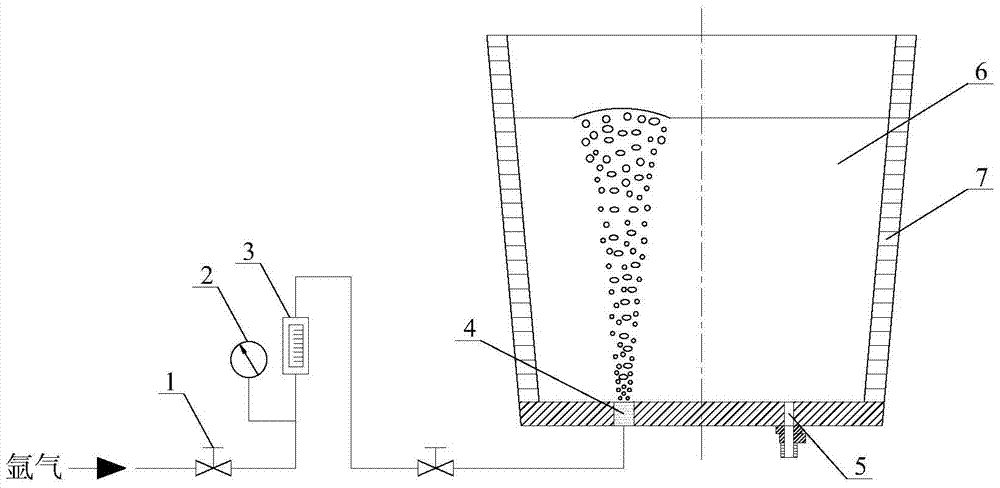
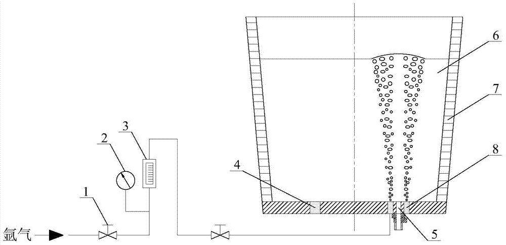
A method of controlling ladle slag by blowing argon gas around the taphole at the bottom of the ladle
A technology of tapping hole and bottom ring, which is applied in the direction of manufacturing tools, casting molten material containers, metal processing equipment, etc., can solve the problems of floating valve consumables, high price, and difficulty in adding drainage sand, so as to prevent slag from entering the tundish , the effect of increasing the yield
- Summary
- Abstract
- Description
- Claims
- Application Information
AI Technical Summary
Problems solved by technology
Method used
Image

Examples
Embodiment 1
[0019] The ladle that adopts in the present embodiment is 50 tons.
[0020] During the pouring process of the ladle, when the liquid level of the molten steel in the ladle is 150mm, the argon blowing pressure is controlled to be 0.2MPa, and the argon blowing flow rate is 1Nm 3 / h, so that argon gas is blown into the molten steel through the ring-shaped breathable brick. The breathable width of the ring-shaped breathable brick is 50mm, which can suppress the slag from the ladle and increase the yield of molten steel in the ladle pouring process.
[0021] Using the above process parameters, compared with the traditional ladle leaving steel operation to control the slag lowering process, the molten steel yield in the ladle pouring process is increased by 14%.
Embodiment 2
[0023] The ladle that present embodiment adopts is 80 tons.
[0024] During the pouring process of the ladle, when the liquid level of the molten steel in the ladle is 220mm, the argon blowing pressure is controlled to be 0.4MPa, and the argon blowing flow rate is 11Nm 3 / h, so that argon gas is blown into the molten steel through the annular air-permeable brick. The air-permeable width of the annular air-permeable brick is 150mm, which can suppress the slag from the ladle and increase the yield of molten steel during the ladle pouring process.
[0025] Using the above process parameters, compared with the traditional ladle leaving steel operation to control the slag lowering process, the molten steel yield in the ladle pouring process is increased by 15%.
Embodiment 3
[0027] The ladle that present embodiment adopts is 180 tons.
[0028] During the pouring process of the ladle, when the liquid level of the molten steel in the ladle is 400mm, the argon blowing pressure is controlled at 0.7MPa, and the argon blowing flow rate is 20Nm 3 / h, so that argon gas is blown into the molten steel through the annular air-permeable brick. The air-permeable width of the annular air-permeable brick is 300mm, which can suppress the slag of the ladle and increase the yield of molten steel during the ladle pouring process.
[0029] Using the above process parameters, compared with the traditional ladle leaving steel operation to control the slag lowering process, the molten steel yield in the ladle pouring process is increased by 17%.
PUM
 Abstract
Description
Claims
Application Information