AI technical title is built by PatSnap AI team. It summarizes the technical point description of the patent document.
A molten steel and pressure technology, applied in the field of metallurgy, can solve problems such as slag protrusion, lower molten steel quality, and unusable residual steel, and achieve the effects of reducing processing costs, improving molten steel quality, and improving steelmaking production efficiency
Active Publication Date: 2021-11-26
万恩同
View PDF10 Cites 0 Cited by
Summary
Abstract
Description
Claims
Application Information
AI Technical Summary
This helps you quickly interpret patents by identifying the three key elements:
Problems solved by technology
Method used
Benefits of technology
Problems solved by technology
[0004] For some high-grade steel types, steel mills often adopt the method of sacrificing the yield of molten steel and closing the nozzle in advance, resulting in a large amount of residual steel in the converter, ladle, and tundish that cannot be used; In this case, the steel slag is allowed to mix into the molten steel, although the yield of molten steel is improved, but the quality of molten steel is reduced
[0005] However, as the pace of steel production accelerates, the transfer speed of molten steel also accelerates. It is necessary to increase the diameter of various nozzles, which leads to more prominent problems of slag discharge.
Method used
Image
Click on the blue label to locate the original text in one second.
Reading with bidirectional positioning of images and text.
Examples
Embodiment 1
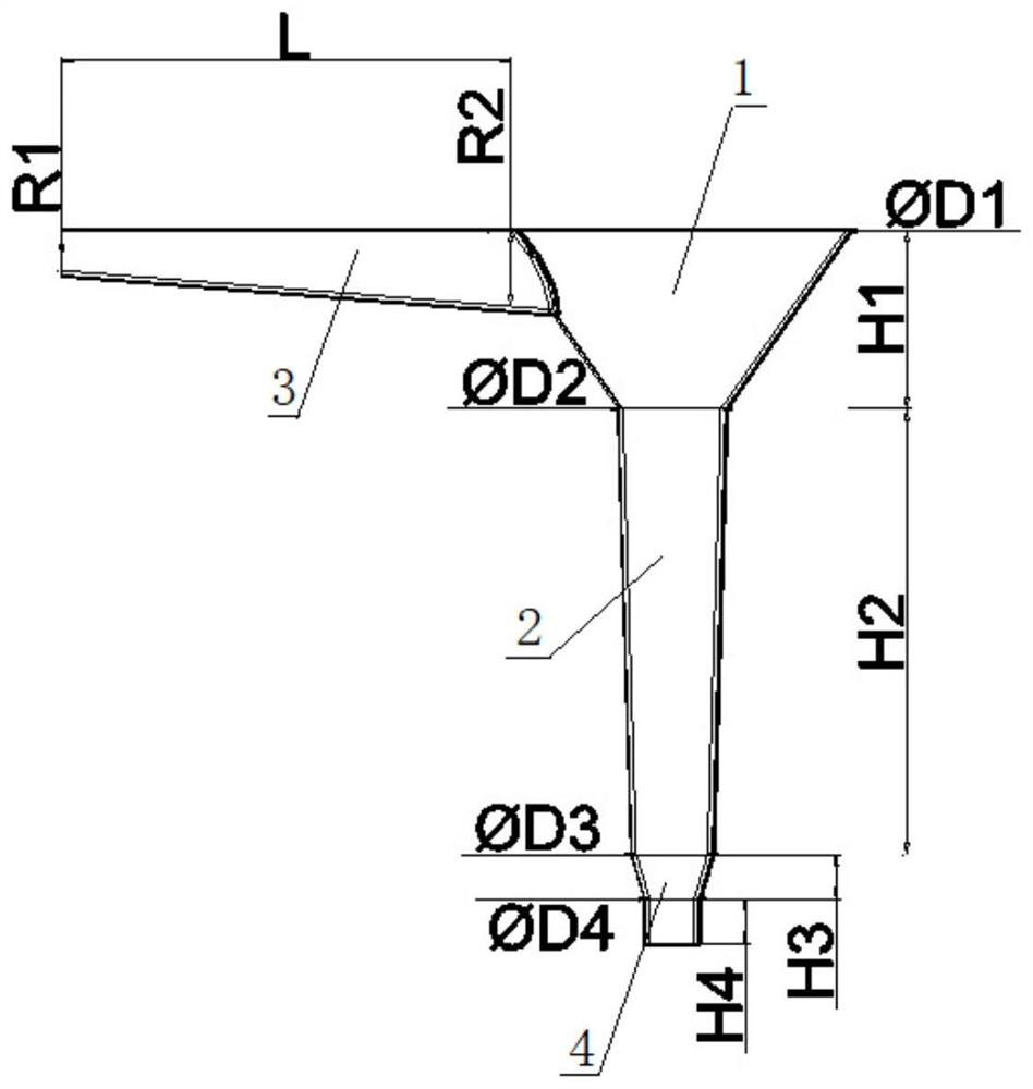
[0061] Embodiment 1: A positive pressure strong nozzle, R1=20mm, R2=30mm, L=150mm, three slope-shaped diversion grooves 3, evenly distributed around the molten steel convergence area 1; D1=120mm, D2=60mm, H1= 60mm, D3=40mm, H2=250mm, D4=35mm, H3=20mm, H4=20mm, the exhaustion time is 23s, the critical height of the vortex is about 30mm, and the tapered transition section 2 is from top to bottom 1 / 4, 1 / Drill three small holes at the 2nd and 3 / 4th places. When the valve is opened, it can be seen that the water flows out from the small holes, and the water flow ranges in turn. It shows that the water flow produces a positive pressure, and the positive pressure at the lower part of the nozzle is greater;
Embodiment 2
[0062] Embodiment 2: A positive pressure strong nozzle, R1=20mm, R2=40mm, L=150mm, three slope diversion grooves 3, evenly distributed around the molten steel convergence area 1, D1=200mm, D2=70mm, H1= 80mm, D3=50mm, H2=350mm, D4=40mm, H3=20mm, H4=20mm, exhaustion time 21s, vortex critical height<40mm, vortex intensity is weak, stream is regular flow, weak impact on the next container, The sound is small, and the number of bubbles entering the water is large and small;
Embodiment 3
[0063] Embodiment 3: A positive pressure strong nozzle, R1=20mm, R2=40mm, L=150mm, three slope diversion grooves 3, evenly distributed around the molten steel convergence area 1, D1=240mm, D2=70mm, H1= 80mm, D3=50mm, H2=400mm, D4=40mm, H3=20mm, H4=150mm, exhaustion time 18s, vortex critical height<40mm, slightly larger than Example 2, vortex intensity is weak, stream is regular flow, The impact on the next container is weak, the sound is small, and the number of bubbles entering the water is large and small.
PUM
Abstract
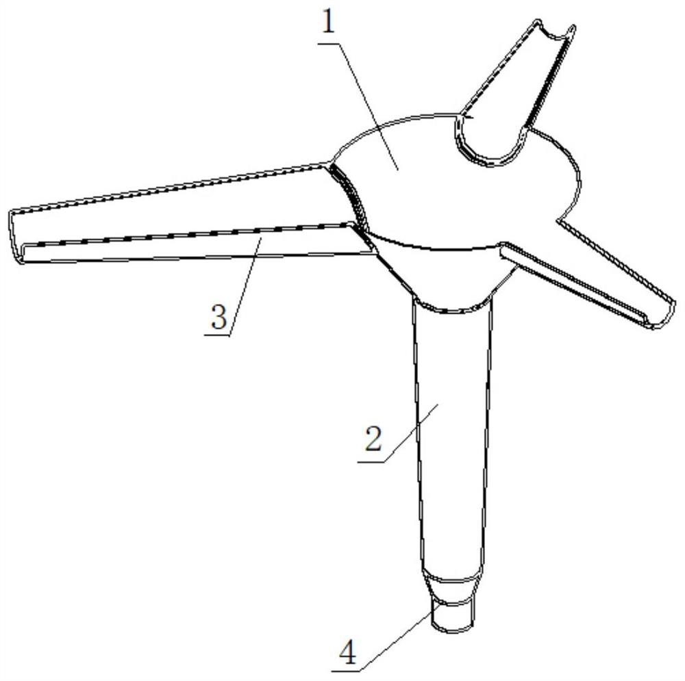
The invention relates to the field of metallurgy technology, and discloses a positive pressurenozzle for molten steel transfer, which includes a molten steel converging area and a conical transition section arranged sequentially in a sealed manner along the molten steel flow direction, and the molten steel converging area and the conical transition section are both The upper part is large and the lower part is hollow and rounded, and it also includes 1 to 4 slope-shaped diversion grooves. The slope-shaped diversion groove is a horizontal semi-circular platform structure, and the deeper end of the slope-shaped diversion groove is connected to the molten steel convergence area. , and the upper surface of the slope-shaped diversion groove is flush with the upper surface of the molten steel converging area, and the line of the slope-shaped diversion groove passing through the center of the molten steel converging area in the incoming flow direction is the axis of symmetry, and is symmetrically distributed around the molten steel converging area. The positive pressurenozzle used for molten steel transfer in the present invention reduces the critical height of the vortex, greatly reduces the amount of steel slag involved in molten steel, improves the quality of molten steel, increases the output of molten steel, and reduces the cost of refining and processing molten steel.
Description
technical field [0001] The invention relates to the technical field of metallurgy, in particular to a positive pressurenozzle for transferring molten steel. Background technique [0002] In steel production, molten steel is continuously transferred from one container to another, and each container has corresponding slag due to the needs of smelting: there is steel slag in the converter, ladle slag in the ladle, and tundish slag in the tundish. In order to avoid affecting the steel production process and steel quality, it is necessary to minimize the flow of slag into the next container. [0003] The reason why the slag is transferred with the molten steel through the nozzle is due to the vortex phenomenon in the liquid flow. The vortex is a common phenomenon in our life, which is caused by the inconsistency of the flow velocity between adjacent particles during the flow of the fluid. Above the vertical nozzle, when the liquid reaches a certain critical height, a visible v...
Claims
Application Information
Patent Timeline
Application Date:The date an application was filed.
Publication Date:The date a patent or application was officially published.
First Publication Date:The earliest publication date of a patent with the same application number.
Issue Date:Publication date of the patent grant document.
PCT Entry Date:The Entry date of PCT National Phase.
Estimated Expiry Date:The statutory expiry date of a patent right according to the Patent Law, and it is the longest term of protection that the patent right can achieve without the termination of the patent right due to other reasons(Term extension factor has been taken into account ).
Invalid Date:Actual expiry date is based on effective date or publication date of legal transaction data of invalid patent.

