
Method for electromagnetically controlling steel ladle drainage and vortex slag entrapment at last stage of molten steel pouring
An electromagnetic control, ladle technology, applied in the direction of manufacturing tools, casting melt containers, metal processing equipment, etc., can solve the problems of reducing the cleanliness of molten steel, reducing the yield of molten steel, and low self-opening rate of ladle, and improving the recovery of molten steel. High yield, fast heating speed, and the effect of reducing slag entrainment
- Summary
- Abstract
- Description
- Claims
- Application Information
AI Technical Summary
Problems solved by technology
Method used
Image

Examples
Embodiment Construction
[0035] Below, the present invention will be further described in detail in conjunction with the accompanying drawings and specific implementation examples. However, the scope of protection of the present invention is not limited by specific implementations.
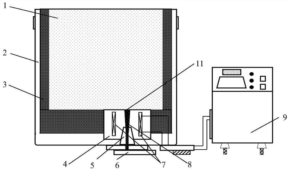
[0036] The structure of the device of the present invention is as figure 1 As shown, it mainly includes a seat brick 4, an upper nozzle 5, a slide plate 6, and an induction coil 7.
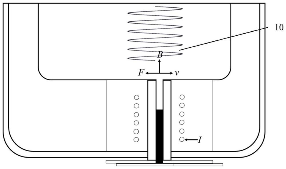
[0037] In the ladle manufacturing or rebuilding stage, the block 4 encapsulating the induction coil 7 is built at a designated position in the bottom substrate 3 of the ladle 2 , and the induction coil 7 is arranged around the upper nozzle 5 . The casting hole 11 at the center of the block brick communicates with the upper nozzle 5 . Before being packaged into the seating brick 4, the surroundings of the induction coil 7 are covered with heat insulating material. A slide plate 6 is arranged at the bottom of the upper nozzle 5 . The induct...
PUM
| Property | Measurement | Unit |
|---|---|---|
| thickness | aaaaa | aaaaa |
| height | aaaaa | aaaaa |
Abstract
Description
Claims
Application Information