
Integral Orbiting CubeSat Launcher

A launcher and orbital technology, applied in the field of integral orbital cubesat launcher, can solve problems such as excessive rotation, reverse recovery of the hatch, damage, etc., and achieve the effect of ensuring stability and increasing applicability

Active Publication Date: 2016-09-21
NANJING UNIV OF SCI & TECH
View PDF5 Cites 7 Cited by
  • Summary
  • Abstract
  • Description
  • Claims
  • Application Information

AI Technical Summary

Problems solved by technology

[0005] (1) Cost problem: the structure is exquisite and complex, and the processing cost and processing accuracy are high;
[0006] (2) The problem of hatch rotation: when the unlocking device is unlocked, the hatch opens and may rotate excessively, colliding with the carrying platform, causing unnecessary damage;
[0007] (3) Anti-restoration of the cabin door: During the release process of the microsatellite, if the cabin door recovers during the rotation process, it will affect the release of the microsatellite, and may even cause damage to the microsatellite;
[0008] (4) The problem of push plate coming out: the push plate is between the compression spring and the micro-satellite, and the small satellite is pushed out of the release device by using the energy inside the compression spring. When the small satellite is completely released, the push plate may come out of the release device under the action of inertia;
[0009] (5) Applicability issues: the current satellite release device is not very versatile, and it is only suitable for small satellites that are square and without any additional devices
[0010] (6) The problem of the degree of freedom of the micro-satellite: During the launch process of the launch vehicle, the stress environment is relatively complicated. If the micro-satellite has no degree of freedom restriction measures, it will run around in the launch device, which may cause damage to the device and the small satellite.

Method used


Image

  • Integral Orbiting CubeSat Launcher
  • Integral Orbiting CubeSat Launcher
  • Integral Orbiting CubeSat Launcher

Examples


Embodiment

[0056] combine Figure 1 to Figure 14

[0057] In the following, for convenience, the 1-unit CubeSat is referred to as 1U, the 2-unit CubeSat is referred to as 2U, and the 3-unit CubeSat is referred to as 3U.

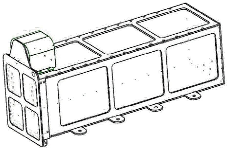
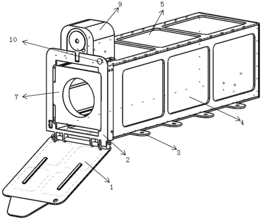
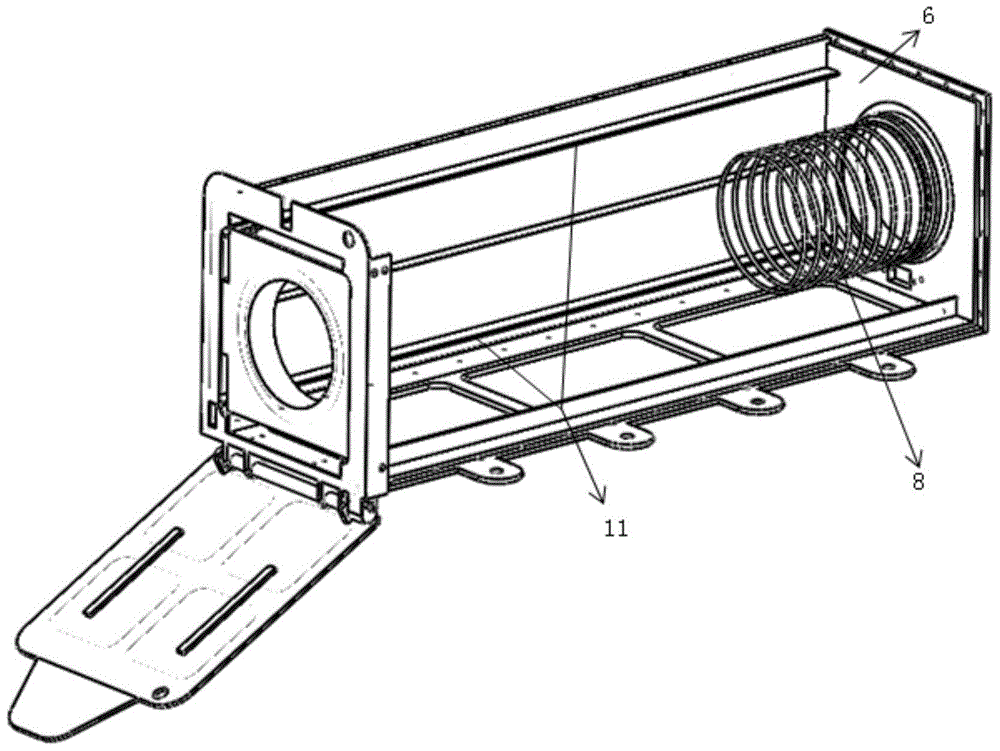
[0058] An integral orbital cubesat launching device, comprising a main frame, a spring mechanism, and an unlocking mechanism; the main frame includes a cabin door 1, a door baffle plate 2, a bottom plate 3, a side plate 4, an upper cover plate 5 and a rear cover 6, and the side plate 4 are symmetrically installed on both sides of the bottom plate 3, and the upper cover plate 5 is installed on the top of the side plate 4. The four plates are symmetrically distributed along the long axis with thin bosses 11, and the slide rails are formed in pairs. Cover 6, the bottom end of the door baffle plate 2 exceeds the position of the bottom plate 3 to set the shaft seat, and the shaft seat is fixedly provided with the hatch rotating shaft, and the hatch door 1 rotates and cooper...


PUM


Abstract

The invention discloses an integrated rail type cube satellite launching device used to carry or launch a single or multiple cube satellites. The integrated rail type cube satellite launching device mainly comprises a rectangular frame, an unlocking mechanism, a spring mechanism and the like, wherein the rectangular frame is mainly formed by connecting a cabin door, a baffle, a bottom plate, side plates, an upper cover plate, a rear cover plate and the like through threads. An upper plate, a lower plate, a left plate and a right plate are symmetrically distributed along the long axis and form a thin boss, and each two of the upper plate, the lower plate, the left plate and the right plate form an integrated type rail used as a satellite slide rail. Components of a sucker magnet and the like are used as an unlocking mechanism. A spring mechanism comprises a push plate and a press spring. The integrated rail type cube satellite launching device is strong in universality and low in cost, can guarantee transportation safety and launching reliability of the cube satellites, can prevent the cube satellites from shifting during the transportation process, prevents the cabin door from striking a revolving platform or reversely revolving during the opening process, and provides push plate ejection prevention measures and the like.

Description

technical field [0001] The invention belongs to the technical field of standard cubesat carrying and launching, in particular to an integral orbit type cubesat launching device. Background technique [0002] With the development of microelectronics technology, new materials, new energy and other technologies, the application of microsatellites has developed rapidly. At present, they are mainly used for communication, remote sensing of the earth, interplanetary exploration, scientific research and technical experiments, etc., and also have military applications. Wide application prospects, so many countries have included it in the national research plan, as a commanding height of technology and economic development in the 21st century. my country Aerospace Dongfanghong Satellite Company, Shanghai Microsatellite Engineering Center of the Chinese Academy of Sciences, National University of Defense Technology, Tsinghua University, Harbin Institute of Technology, Zhejiang Univers...

Claims


Application Information

Patent Timeline
Patent Type & Authority Patents(China)
IPC IPC(8): B64G1/64
Inventor 沈娜包家倩张祥金廖桥生吴志亮
Owner NANJING UNIV OF SCI & TECH
Learn More