Lift bridge

A lifting bridge and bridge body technology, which is applied in the direction of bridges, vertical bridges, bridge forms, etc., can solve the problems of inability to carry out large-scale lifting, small adjustable amount, and inapplicability

Active Publication Date: 2015-04-22
THE JIANGSU GENERAL FACTORY OF WATER CONSERVANCY MACHINERY
View PDF7 Cites 10 Cited by
  • Summary
  • Abstract
  • Description
  • Claims
  • Application Information

AI Technical Summary

Problems solved by technology

Its shortcoming is: this device is applicable to urban road traffic, but can not be applicabl

Method used


Image

  • Lift bridge
  • Lift bridge
  • Lift bridge

Examples


Embodiment Construction

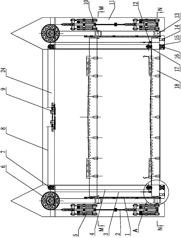
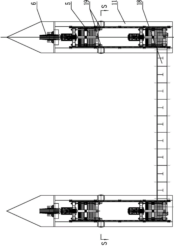
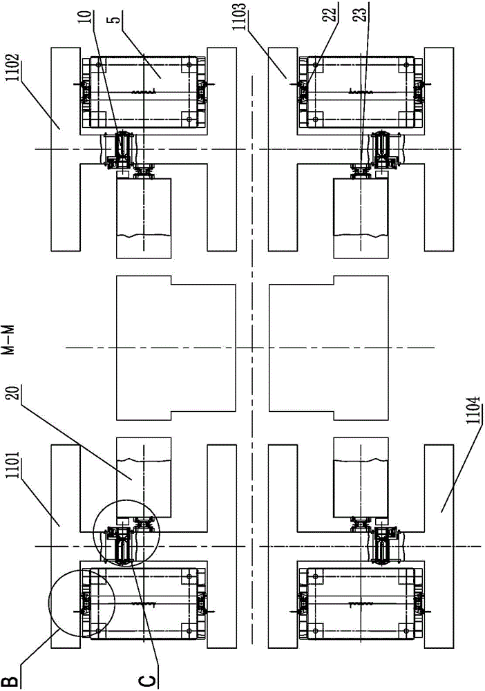
[0023] Such as Figure 1-8 As shown, it is a lifting bridge, the bridge body 18 is horizontally arranged above the river, and two supporting towers 11 are respectively arranged on both sides of the river, and there are four in total. image 3 are respectively marked as the first support tower 1101, the second support tower 1102, the third support tower 1103 and the fourth support tower 1104; A movable pulley block 17 is provided, and a fixed pulley block 7 is arranged on the upper part of the support tower 11. A crossbeam 24 is fixed between the support towers 11 on the same side of the river bank, and a driving device 9 is installed on the crossbeam 24. The crossbeam 24 on each side of the river bank is respectively There are two groups of driving devices, each group of driving devices includes a motor 903, a reducer 904 and a rope drum 901, the output shaft of the motor 903 is connected to the rope drum 901 through the reducer 904, and the output shafts of the two motors 903...


PUM


Abstract

The invention discloses a lift bridge and belongs to the technical field of bridges. The lift bridge comprises a horizontal bridge body arranged above a river channel. The two sides of the river channel are each provided with two supporting towers, the four corners of the bridge body are each provided with a lift arm, and the upper side of each lift arm is provided with a movable pulley block. The upper portions of the supporting towers are provided with fixed pulley blocks. A crossbeam is fixed between the supporting towers on the same side of a river bank, each crossbeam is provided with a drive device which comprises a rotary rope tube, and a lift wire rope is wound around the fixed pulley blocks and the movable pulley blocks to be wound around the rope tube. Each lift arm is further provided with an anchoring piece which is connected with one end of a balance wire rope, the upper portion of each supporting tower is further provided with a reversing guide wheel, the balancing wire ropes are wound around the reversing guide wheels, and balance weights are connected to the other ends of the balance wire ropes. In work, the balance weights can balance most gravity of the bridge body, the drive mechanism can ascend and descend the bridge body just with low power, and the lift bridge is simple in structure and low in operation energy consumption, and can be applied to the river channels which need to be open to navigation frequently.

Description

technical field [0001] The invention relates to a bridge device, in particular to a liftable bridge device. Background technique [0002] In the Chinese patent database, there is a balanced motorized lifting bridge, its application number: 90110096.X, application date: 1990-12-21, publication number: CN1052643; publication date: 1991-07-03, the two ends of the bridge body of the device Set bridge boxes symmetrically, one or two at each end. The bridge is composed of bridge boxes, operating platform, steel wire rope, hoistway column, bridge body, beam, beam plate, wire rope wheel, main beam and auxiliary power unit. The bridge body and main beam Supported by shaft columns or piers, one or two bridge boxes are installed at both ends of the bridge body. An operating platform is installed in the bridge box. on wheels. It adopts the shaft structure perpendicular to the ground to make the bridge box lift up and down to convey the flow of people and vehicles, and cancels the appr...

Claims


Application Information

Patent Timeline
IPC IPC(8): E01D15/02
CPCE01D15/02
Inventor 王兵凌建顾明如何世明王波崔兴华戴科荣顾世民张文涵汤翠芳
Owner THE JIANGSU GENERAL FACTORY OF WATER CONSERVANCY MACHINERY
Why Eureka
Try Eureka