Wireless Optical Touch Screen System and Its Application

An optical touch screen, wireless technology, applied in the computer field, can solve the problems of inconvenient installation, no selectivity, waste, etc., and achieve the effect of convenient installation and free choice.

Active Publication Date: 2018-02-27
隋美青
View PDF8 Cites 0 Cited by
  • Summary
  • Abstract
  • Description
  • Claims
  • Application Information

AI Technical Summary

Problems solved by technology

[0002] The existing touch screen system is not easy to install, so most of the equipment that needs to be installed with the touch screen system has already installed the touch screen system on the equipment before leaving the factory
As a result, end customers have no choice as to whether there is a touch screen system on the device
[0003] Some equipment is equipped with a touch screen system in advance, but the customer does not need it. This situation is a waste for both the customer and the manufacturer.
Some equipment is not equipped with a touch screen system in advance, but the customer needs to use the touch screen system. In this case, the customer may choose other products, or need to spend a high cost to modify the equipment. This situation is also harmful to customers and manufacturers. Unfavorable, the manufacturer may lose customers, and customers may spend more

Method used


Image

  • Wireless Optical Touch Screen System and Its Application
  • Wireless Optical Touch Screen System and Its Application
  • Wireless Optical Touch Screen System and Its Application

Examples


specific Embodiment 1

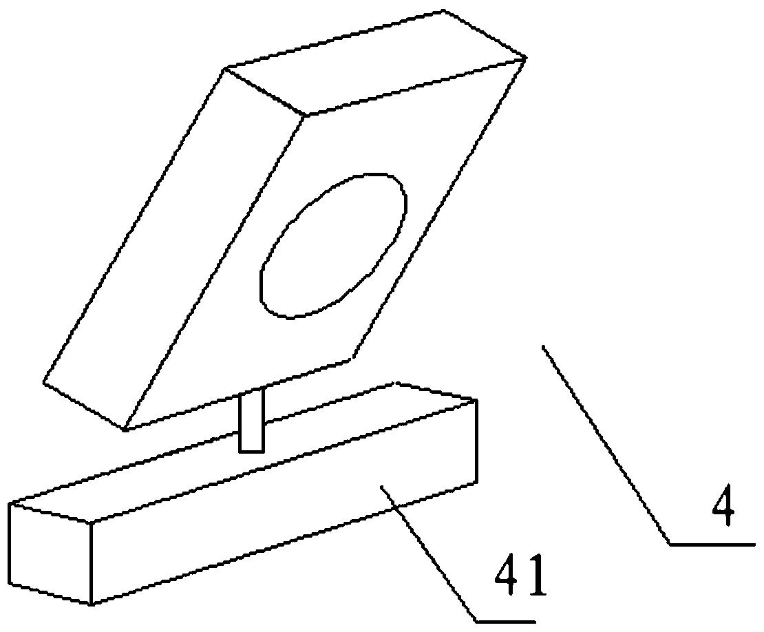
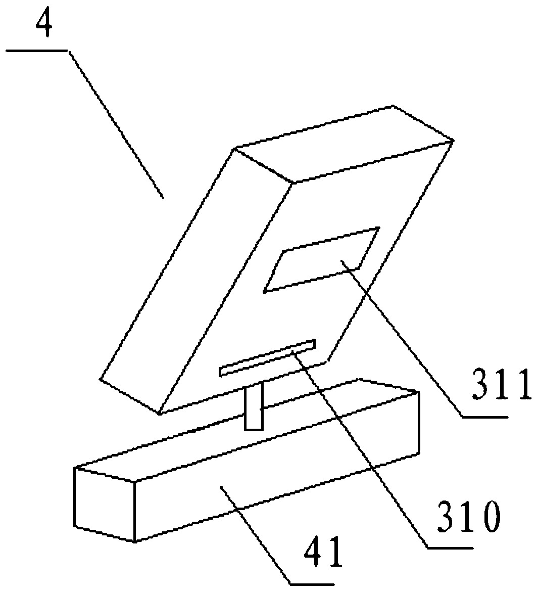
[0045] refer to image 3 The touch position detection module 3 may be a touch position detection module that adopts the structural principle of the click position detection module for determining the click position, which is adopted by the existing virtual laser keyboard. It includes an infrared emitting source 310 and an infrared signal receiving module 311 . An infrared image positioning device is arranged inside, and the infrared signal receiving module 311 is connected to the infrared image positioning device. In order to eliminate the signal blind area at a short distance, the optical signal receiving part of the infrared signal receiving module 311 is relatively protruding and inclined downward.

[0046] The click position detection module adopted in the existing virtual laser keyboard can better detect the click position and accurately locate it. It can be directly applied to the present invention to detect and locate the touch point. The click position of the virtua...

specific Embodiment 2

[0052] The touch position detection module 3 can also determine the touch point by adopting the technical solution described in the patent titled "Laser Remote Control Signal Receiver and Its Supporting Laser Remote Control Signal Transmitter" and the application number is 200810035508.x The position of the touch position detection module 3. This needs to be used in conjunction with a dedicated touch pen that can emit light beams. Take the light point presented by the light beam on the display screen 6 as the touch point.

[0053] refer to Figure 5 , Image 6 The touch position detection module 3 includes a photosensitive element group, and the photosensitive element group includes at least two photosensitive elements, and the photosensitive element group is covered with an optical signal directional receiving device 321 for filtering non-correlated direction optical signals. The photosensitive element 320 is connected to a signal processing module 322 for processing elect...

specific Embodiment 3

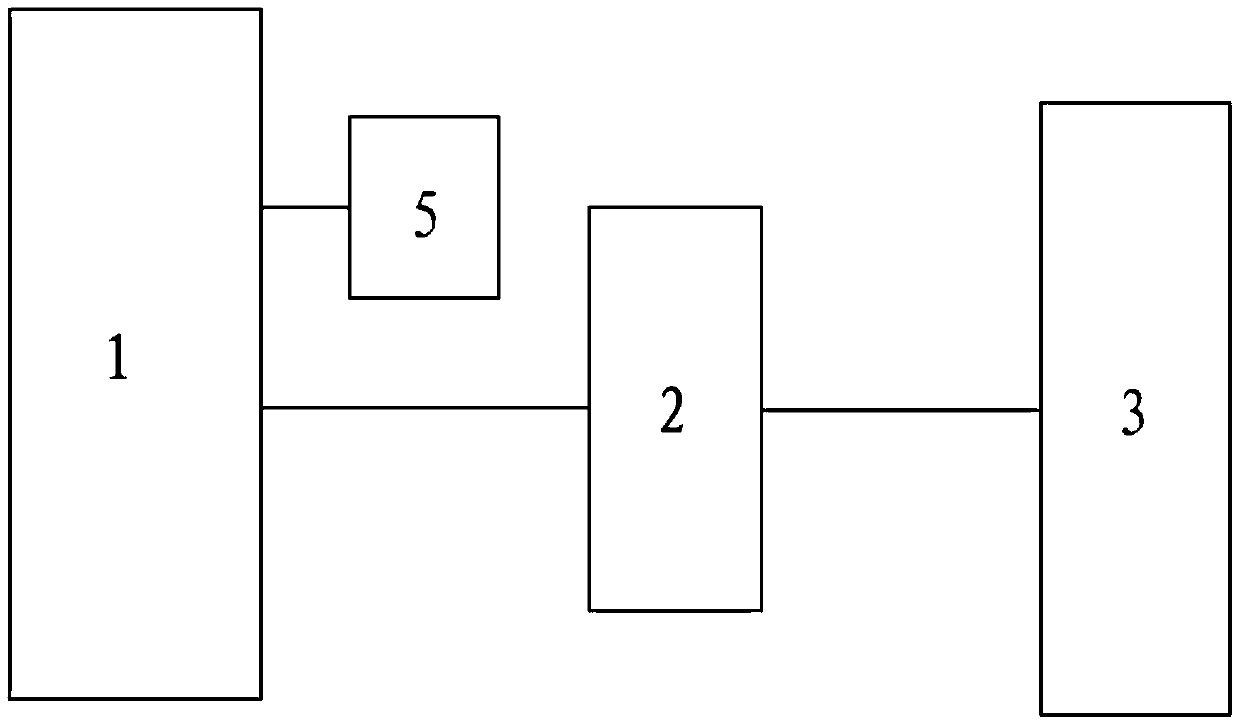
[0059] refer to Figure 8 , the touch position detection module 3 includes a camera 33 for capturing images on the display screen 6 . The camera device 33 is connected to the microprocessor module 1 and transmits the touch point image to the microprocessor module 1 . The microprocessor module 1 is a microprocessor module 1 capable of determining the position of the touch point through the image of the touch point. Existing image interaction technologies can already fulfill the above technical requirements well, so no more details are given here.

[0060] It can be applied to mobile phones, handheld computers, desktop computers, projector systems and other equipment. Especially for the projector system, it can realize the remote control of the host computer at the screen. In order to further reduce or even eliminate blind spots, the above design is particularly easy to install at the corner of the display screen 6 .


PUM


Abstract

The invention relates to the field of computers, in particular to a touch screen system. The wireless optical touch screen system comprises a micro-processor module, a communication module, a touch position detection module and a fixing device, wherein the communication module is in communication with the micro-processor module; the touch position detection module is used for detecting the position of a touch point; the fixing device is used for fixing the wireless optical touch screen system to one side or one corner of a screen; the touch position detection module is used for detecting the position of the touch point according to optical characteristics; the wireless optical touch screen system comprises a shell; the communication module and the touch position detection module are mounted in the shell; a Bluetooth mode is adopted for the communication module, so the system is more concise and more convenient to mount and demount.

Description

technical field [0001] The invention relates to the computer field, in particular to a touch screen system. Background technique [0002] The existing touch screen system is not easy to install, so most of the equipment that needs to be installed with the touch screen system has already installed the touch screen system on the equipment when leaving the factory. As a result, end customers have no choice as to whether there is a touch screen system on the device. [0003] Some equipment is equipped with a touch screen system in advance, but the customer does not need it. This situation is a waste for both the customer and the manufacturer. Some equipment is not equipped with a touch screen system in advance, but the customer needs to use the touch screen system. In this case, the customer may choose other products, or need to spend a high cost to modify the equipment. This situation is also harmful to customers and manufacturers. Unfavorable, the manufacturer may lose custo...

Claims


Application Information

Patent Timeline
Patent Type & Authority Patents(China)
IPC IPC(8): G06F3/042
CPCG06F3/0421
Inventor 李兴文孙倩倩李兴武孙斌斌邢明阳任颖倩许振民李文杰
Owner 隋美青
Why Eureka
Try Eureka