
Nursing device

A nursing device and pillar technology, applied in medical science, hospital beds, hospital equipment, etc., can solve the problems of poor ease of use, unreasonable combination, poor ease of use, etc., and achieve the effect of improving ease of use and safety

Active Publication Date: 2015-04-29
PARAMOUNT BED CO LTD
View PDF14 Cites 1 Cited by
  • Summary
  • Abstract
  • Description
  • Claims
  • Application Information

AI Technical Summary

Problems solved by technology

[0012] 1. In the nursing device using the support rod, the range of the support rod can be grasped is narrow, and there are many parts divided by the pillars, etc., and the action of changing hands must be performed during the standing up, sitting down and transfer actions, which is not easy to use
[0013] 2. In a device configured with a pillar in order to rotate the body around the pillar, there may be a problem that clothes are caught on the top end of the pillar due to the height of the pillar
[0014] 3. In the device that only uses the planar support part, in order to make the supporting area sufficiently large, the plate-shaped body itself must be enlarged. In addition, in the structure of this plate-shaped body, it cannot be grasped like a support rod. Sit up, sit down and transfer movements
[0015] 4. As in the above-mentioned Patent Document 1, although the two sides of the support rod and the pad of the planar support part are also used, they are not in the same plane shape and are not rationally combined, so the usability is poor, and as shown in item 3 In that case, in order to make its supporting area large enough, the pad itself must be made larger
[0016] 5. In the past nursing devices, the pillars supporting the main body of the nursing device are basically only upright structures. Risk of being caught in the gap in the event of a fall
[0017] 6. Failure to properly set support rods, pads or pillars, etc. as required

Method used


Image

  • Nursing device
  • Nursing device
  • Nursing device

Examples


Embodiment Construction

[0114] Below, refer to the attached Figure 1-18 Embodiments of the present invention will be described. In addition, in Figure 1 to Figure 18 In , the corresponding structural elements are marked with the same symbols.

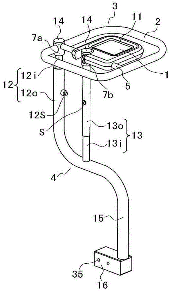
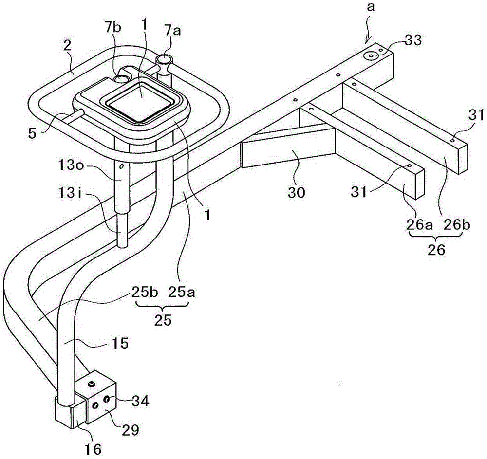
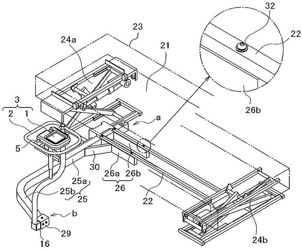
[0115] The nursing device of the present invention is configured such that the planar support part 1 and the ring-shaped frame part 2 are combined in substantially the same plane to form a care support body 3, and the ring-shaped frame part 2 is arranged on the planar support part at intervals. 1, the support body 3 for care is supported by pillars 4 erected.

[0116] That is, in the present embodiment, the care support body 3 is formed by combining the rod body 5 disposed so as to deviate from the planar support portion 1 side, and the ring-shaped frame portion 2 . That is, the rod body 5 is biased between the sides of the substantially rectangular annular frame portion 2 and coupled thereto, and constitutes the small frame portion 6 at the middle portio...


PUM


Abstract

Provided is a nursing device. A plane-shaped support part (1) and an annular framework part (2) are combined in the same panel largely so that a nursing support body (3) is formed. Vertically arranged struts which are disposed around the panel-shaped support part (1) at intervals are left on the annual framework part (2) so as to support the nursing support body (3). The lower parts of the struts (4) are fixed and vertically arranged on a lying bench of a bed or a sofa. In addition, the struts can be vertically arranged into a self-standing type structure. According to the invention, a problem of poor convenience caused by a failure of proper combination of support rods and protection pads of the panel-shaped support parts in a former nursing device is solved.

Description

technical field [0001] The present invention relates to a nursing device which is installed near a supine table such as a bed or a treatment table or a sofa, etc., and is used for assisting a care recipient or a patient in standing up, sitting down, and transferring to a wheelchair, etc. wait. Background technique [0002] For example, in the past, various nursing devices have been proposed so that the care receivers and patients who use supine platforms such as beds can stand up from the state of sitting on the side of the supine platform, or vice versa. When performing the action of sitting down, or performing the action of transferring to a wheelchair, etc., these actions can be easily and reliably performed. [0003] As a type of this nursing device, various nursing devices have been proposed in the past: the supine platform installation type nursing device, its structure is that the extended setting parts are fixed on the frame of the supine platform, and the extended ...

Claims


Application Information

Patent Timeline
IPC IPC(8): A61G7/05
Inventor 池田健一马野顺司松本孝树佐佐木由理下村晃生永易武
Owner PARAMOUNT BED CO LTD
Learn More