Blast furnace top airtight box sealing device

A sealing device, blast furnace technology, applied in blast furnace, blast furnace details, blast furnace parts and other directions, can solve the problems of high production and use cost, poor sealing effect, inability to effectively prevent waste gas from entering the cavity of the airtight box, etc. Low production cost and good sealing effect

Inactive Publication Date: 2015-04-29
JIANGSU YONGGANG GROUP CO LTD
View PDF5 Cites 5 Cited by
  • Summary
  • Abstract
  • Description
  • Claims
  • Application Information

AI Technical Summary

Problems solved by technology

Since there will be a gap between the bottom plate of the airtight box shell and the rotating sleeve, in order to prevent the raw gas (mainly composed of carbon monoxide, carbon dioxide, methane and dust) in the blast furnace from entering the cavity of the airtight box from being damaged The driving parts in the cavity are usually gas-sealed, that is, nitrogen is filled into the cavity of the airtight box, so that the pressure in the cavity of the airtight box is slightly higher than the pressure of the blast furnace top (that is, the blast furnace raw gas Pressure), so as to achieve the purpose of sealing the cavity of the airtight box, but the disadvantage of the gas sealing method of this airtight box is that it can only withstand the top pressure of the blast furnace of 115Kpa, not only the sealing effect is poor, and it cannot effectively prevent the shortage of gas Entering the cavity of the airtight box, and the consumption of nitrogen is large, the production and use cost of the enterprise is high, and the nitrogen passing into the airtight box into the blast furnace will reduce the calorific value of the blast furnace gas and affect the efficiency of the blast furnace

Method used


Image

  • Blast furnace top airtight box sealing device

Examples


Embodiment Construction

[0014] The present invention will be further described below in conjunction with the accompanying drawings and specific embodiments.

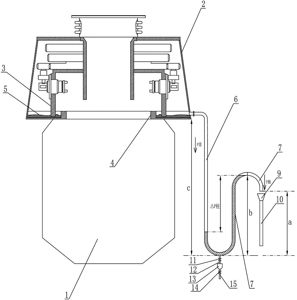
[0015] Such as figure 1 As shown, the described blast furnace roof airtight box sealing device includes: an airtight box shell 2 installed on the top of the blast furnace 1, and a rotating sleeve 3 installed in the airtight box shell 2. The bottom plate of the box shell 2 is provided with a circle of annular baffle 4 around the discharge port. The annular baffle 4 forms an annular water tank with the airtight box shell, and the water 5 is filled in the annular water tank. The lower end of the rotating sleeve 3 is just downward. Insert into the annular water tank and be submerged in the water 5 in the annular water tank. An overflow port is provided on the side plate of the airtight box casing 2 above the water 5 in the annular water tank. The overflow port is connected with the U-shaped water tank set upright The water inlet pipe section 6 of ...


PUM


Abstract

The invention discloses a blast furnace top airtight box sealing device which comprises an airtight box shell and a rotating sleeve, wherein the airtight box shell is mounted at the top of a blast furnace; a circle of ring-shaped baffle is arranged on the bottom plate of the airtight box shell around a discharge hole; the ring-shaped baffle and the airtight box shell form a ring-shaped water channel; water is contained in the ring-shaped water channel; the lower end of the rotating sleeve is exactly inserted downwards into the ring-shaped water channel and immersed in the water in the ring-shaped water channel; an overflow opening is formed in the side plate of the airtight box shell above the water in the ring-shaped water channel; the overflow opening is communicated with the water inlet pipe section of an upright U-shaped water sealing pipe; the water outlet pipe section of the U-shaped water sealing pipe is communicated with a drain pipe; the water column in the water outlet pipe section of the U-shaped water sealing pipe is higher than the water column in the water inlet pipe section so as to ensure that the pressure difference between the water column in the water outlet pipe section and the water column in the water inlet pipe section of the U-shaped water sealing pipe is greater than the sum of the pressure at the top of the blast furnace and the negative-pressure draft generated during the drainage of the drain pipe all the time. The blast furnace top airtight box sealing device has the advantages of being good in sealing property and low in enterprise cost.

Description

technical field [0001] The invention relates to a sealing device for an airtight box at the top of a blast furnace. Background technique [0002] The airtight box is the core component of the blast furnace roof distribution equipment, which is mainly used to drive and control the rotation and tilting of the distribution chute around the center line of the blast furnace to complete the blast furnace distribution. The structure of the airtight box is: including the airtight box shell installed on the top of the blast furnace. The airtight box shell is composed of a bottom plate, a top plate and a side plate. The airtight box communicates with the material tank through the feed port opened on its top plate. In the airtight box shell, a rotating sleeve for installing the distribution chute is movable and sealed. The upper end of the rotating sleeve is connected to the airtight box. The casing is sealed and flexibly connected, the upper port of the rotating sleeve faces the feed...

Claims


Application Information

Patent Timeline
Patent Type & Authority Applications(China)
IPC IPC(8): C21B7/00
CPCC21B7/00
Inventor 闻海涛李彬张宁宁祁士明陆建东
Owner JIANGSU YONGGANG GROUP CO LTD
Why Eureka
Try Eureka