Automatic valve structure

An automatic valve and valve technology, which is applied to valve details, valve devices, engine components, etc., can solve the problem of large space occupation, and achieve the effect of solving the problem of excessive space occupation and saving three-dimensional space.

Inactive Publication Date: 2015-04-29
范永禧
View PDF0 Cites 0 Cited by
  • Summary
  • Abstract
  • Description
  • Claims
  • Application Information

AI Technical Summary

Problems solved by technology

[0004] The purpose of the present invention is to provide an automatic valve structure to solve the technical problem that the automatic valve with a cylinder occupies too much space in the prior art

Method used


Image

  • Automatic valve structure

Examples


Embodiment Construction

[0011] In order to make the object, technical solution and advantages of the present invention more clear and definite, the present invention will be further described in detail below with reference to the accompanying drawings and examples.

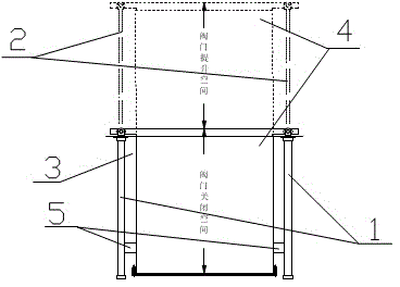
[0012] Such as figure 1 As shown in the structural diagram of the automatic valve structure in the present invention, it includes a cylinder 1 and a valve 3 , the cylinder 1 includes a cylinder body (not shown) and a cylinder rod 2 , and the valve includes a valve body (not shown) and a valve core 4 . There are two cylinders 1, which are arranged on both sides of the valve 3 respectively. The height of the cylinder 1 is the same as that of the valve 3. The two ends of the valve core 4 of the valve 3 are respectively provided with connection positions. The cylinder rods of the two cylinders 1 2 and the connection positions at both ends of the valve core 4 are fixedly connected by bolts, and the valve core 4 moves up and down with the expa...


PUM


Abstract

The invention discloses an automatic valve structure. The automatic valve structure comprises cylinders and a valve. Each cylinder comprises a cylinder body and a cylinder pull rod. The valve comprises a valve body and a valve element. The two cylinders are fixed to the two sides of the valve respectively. Connection positions are arranged at the two ends of the top of the valve element respectively. The cylinder pull rods are connected to the connection positions respectively. The cylinders are arranged on the two sides of the valve, and therefore when the valve is opened, the height of the whole device is only the sum of the height of the valve body and the height of the valve element, and compared with the prior art, the three-dimensional space is saved by one third. The technical problem that in the prior art, the space occupied by an existing automatic valve with cylinders is too large is effectively solved.

Description

technical field [0001] The invention relates to a valve, in particular to an automatic valve structure. Background technique [0002] An automatic valve is arranged at the air inlet of the air handling equipment to control whether the air is fed into the air inlet or not. The structure of the automatic valve generally includes two parts: the valve and the cylinder. The cylinder is installed vertically above the valve, and the valve core moves up and down through the expansion and contraction of the cylinder rod to realize the opening and closing of the valve. The valve with cylinder of this structure, because the valve and the cylinder are stacked and installed in the vertical direction, so the space it occupies is the height of the two valves plus the height of the cylinder, which occupies too much space. Workshops are struggling to meet the requirements. [0003] Therefore, the prior art still needs to be improved and developed. Contents of the invention [0004] The...

Claims


Application Information

Patent Timeline
Patent Type & Authority Applications(China)
IPC IPC(8): F16K31/12
CPCF16K31/12
Inventor 范永禧
Owner 范永禧
Why Eureka
Try Eureka