Gain control device, system and method for silicon photomultiplier

A silicon photomultiplier tube and gain control technology, which is applied in the field of photoelectric detection to achieve the effects of increasing reliability, simple and easy technical solutions, and avoiding feedback systems

Active Publication Date: 2015-04-29
INST OF HIGH ENERGY PHYSICS CHINESE ACADEMY OF SCI
View PDF6 Cites 10 Cited by
  • Summary
  • Abstract
  • Description
  • Claims
  • Application Information

AI Technical Summary

Benefits of technology

This technology simplifies its implementation by eliminating many parts needed for it's purpose but still achieves good accuracy through an algorithm that can adjust temperatures based on factors like ambient conditions or user preferences without requiring expensive equipment such as temperature sensing elements or complex software processes.

Problems solved by technology

This patents describes different types of detectors made up from various materials like crystalline silicon or germanium diode arrays. These devices work well but they require specialized equipment during operation. They use expensive components and may cause issues related to their reliability under extreme conditions. To address this problem, researchers developed SiPM sensors based on other technologies including CCD cameras and MOS image tubes.

Method used


Image

  • Gain control device, system and method for silicon photomultiplier
  • Gain control device, system and method for silicon photomultiplier
  • Gain control device, system and method for silicon photomultiplier

Examples


Embodiment Construction

[0028] Embodiments of the present invention will be described below with reference to the drawings. Elements and features described in one drawing or one embodiment of the present invention may be combined with elements and features shown in one or more other drawings or embodiments. It should be noted that representation and description of components and processes that are not related to the present invention and known to those of ordinary skill in the art are omitted from the drawings and descriptions for the purpose of clarity.

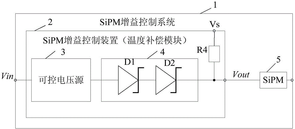
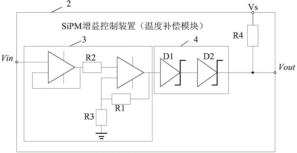
[0029] figure 1 It is a circuit block diagram of the silicon photomultiplier tube gain control device 2 provided according to an embodiment of the present invention. The silicon photomultiplier tube gain control device 2 is essentially a temperature compensation module, including a controllable voltage source 3 connected in series and at least one Zener diode D1, D2. The Zener diode D1, D2 can be replaced by a Zener diode 4. The controllable volt...


PUM


Abstract

The invention relates to a gain control device, a gain control system and a gain control method for a silicon photomultiplier. The gain control device is used for controlling gain of the silicon photomultiplier which is connected in series with the gain control device. The gain control device comprises a controllable voltage source and at least one voltage stabilizing diode which are connected in series, wherein the controllable voltage source comprises at least one input terminal; the voltage stabilizing diode works in a breakdown state; an equivalent temperature coefficient of the voltage stabilizing diode is the same as a temperature coefficient of the silicon photomultiplier; the gain of the silicon photomultiplier is controlled by regulating voltage on the input terminal of the controllable voltage source. A technical scheme adopted by the invention is simple, uses fewer components and parts, and can realize temperature compensation by only needing to use an analog device, so that a temperature sensor, a corresponding digital unit and a corresponding feedback system are cancelled, and the reliability of the system is increased.

Description


Claims


Application Information

Patent Timeline
Owner INST OF HIGH ENERGY PHYSICS CHINESE ACADEMY OF SCI
Why Eureka
Try Eureka