Final drive positioner manufacturing process method

A technology of the main reducer locator and manufacturing process, which is applied in the directions of aircraft parts, transportation and packaging, etc. It can solve the problems of positioning and installation deviation of aircraft main reducer joint products, achieve the effect of no deviation in positioning and installation, and avoid the effect of positioning and installation deviation

Active Publication Date: 2015-05-06
HARBIN
View PDF8 Cites 7 Cited by
  • Summary
  • Abstract
  • Description
  • Claims
  • Application Information

AI Technical Summary

Problems solved by technology

As a result, the positioning and installation deviation of the main reduction joint of the aircraft is caused.

Method used


Image

  • Final drive positioner manufacturing process method
  • Final drive positioner manufacturing process method
  • Final drive positioner manufacturing process method

Examples


Embodiment

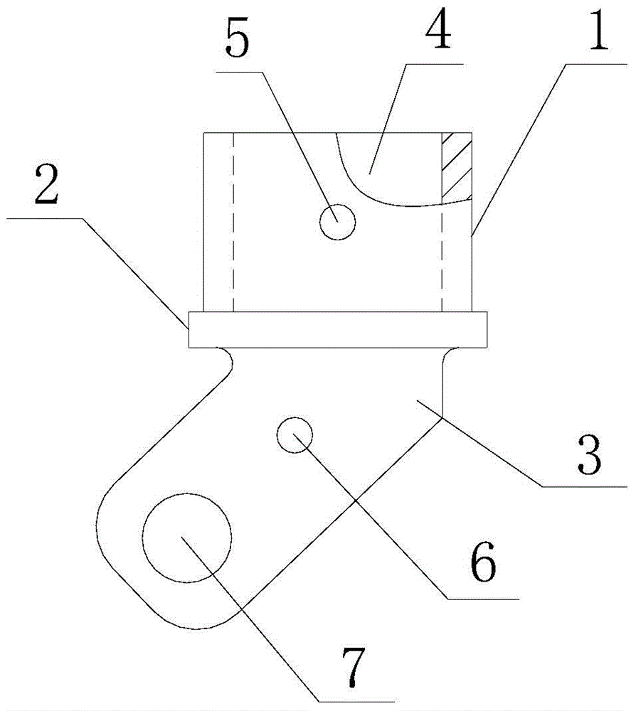
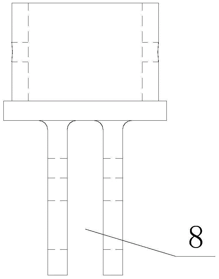
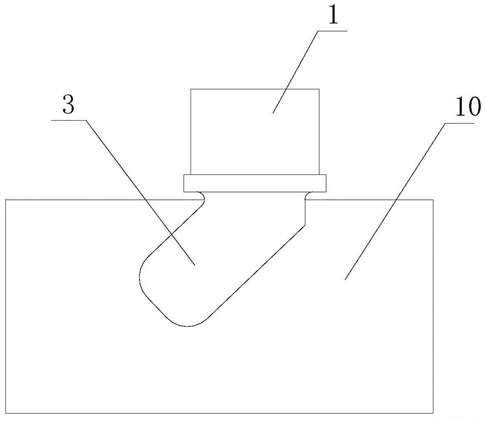
[0051] The length of the positioning sleeve 1 of the main subtractive locator is 60 millimeters, and the inner hole size of the positioning sleeve 1 is mm, the outer circle size of positioning sleeve 1 is mm, the inner diameter of the through hole 5 is mm, the outer diameter of the disc 2 is mm, the thickness of the joint plate 2 is 12 mm, and the inner diameter of the cursor hole 6 is mm, the inner diameter of positioning hole 7 is mm, the width of the positioning groove 8 is 22H7 mm, the thickness of the fork ear 3 is 46H7 mm, the thickness of the ear piece of the fork ear 3 is 12H7 mm, and the vertical distance between the center of the through hole 5 and the center of the cursor hole 6 is 71.48 ±0.02 mm, the horizontal distance between the center of the through hole 5 and the center of the cursor hole 6 is 14.40 ± 0.02 mm, the vertical distance between the center of the through hole 5 and the center of the positioning hole 7 is 106 ± 0.02 mm, the center of the thr...


PUM


Abstract

The invention belongs to an aircraft tool manufacturing process and relates to a final drive positioner manufacturing process method. A vertex of a combined disc is used as a datum point for alignment, a grinding smooth surface of a positioning sleeve is used for positioning, a fork lug is processed on a molybdenum wire cutting machine tool, the shape of the fork lug and the center surface of a positioning groove are used as a benchmark, the positioning sleeve and the combined disc are processed by a digital controlled lathe, an alignment tool plate of which the boundary dimension is larger than that of the fork lug is mutually fixed with a final drive positioner, a method that each hole of the final drive positioner is processed in a computer numerical control boring and milling machine is adopted, an inner groove and an outer shallow of the fork lug of the final drive positioner meet the concentric manufacturing tolerance requirement, the thickness sizes of two flat lug sheets of the fork lug are identical, the thick surfaces are mutually parallel, and the center line of an inner hole of the positioning sleeve coincides with the center surface of the inner groove of the fork lug of a positioning joint. According to the final drive positioner manufacturing process method, the zero deflection of the positioning and mounting of an aircraft final drive joint product is ensured.

Description

technical field [0001] The invention belongs to the manufacturing technology of aircraft tooling, and relates to a manufacturing process method of a main subtractive locator. Background technique [0002] On the tooling for processing the main reduction joint in the transmission system of the helicopter, the main reduction positioner is composed of a positioning sleeve and a positioning joint. Positioning joints include joint discs and fork ears. The positioning sleeve and the positioning joint are connected by welding. The center line of the inner hole of the positioning sleeve is required to coincide with the center of the fork groove of the positioning joint; the center of the inner groove of the fork lug of the positioning joint is required to coincide with the center of the outer flat, and all positioning holes on the fork lug of the positioning joint are required to coincide with the inner garden axis of the positioning sleeve The heart line is vertical. [0003] Th...

Claims


Application Information

Patent Timeline
Patent Type & Authority Applications(China)
IPC IPC(8): B23P15/14
CPCB23P15/14B23P2700/01
Inventor 郭连涛莫文佳郭子瑞郭忠义李辉
Owner HARBIN
Why Eureka
Try Eureka