Pantograph-catenary arc detection method and system based on train power supply system
What is AI technical title?
AI technical title is built by PatSnap AI team. It summarizes the technical point description of the patent document.
A technology of power supply system and electric arc, which is applied in the field of trains and can solve the problems of high energy consumption
Active Publication Date: 2018-09-25
CRRC QINGDAO SIFANG CO LTD
View PDF4 Cites 0 Cited by
Summary
Abstract
Description
Claims
Application Information
AI Technical Summary
This helps you quickly interpret patents by identifying the three key elements:
Problems solved by technology
Method used
Benefits of technology
Problems solved by technology
[0005] The main purpose of the present invention is to provide a pantograph-catenary arc detection method and system based on the train power supply system, to solve the problem in the pantograph-catenary arc simulation test method in the prior art, in order to generate high voltage and large current in the pantograph-catenary gap, High-voltage AC voltage source is used for power supply, resulting in technical problems of high energy consumption
Method used
Image
Click on the blue label to locate the original text in one second.
Reading with bidirectional positioning of images and text.
Examples
Embodiment 1
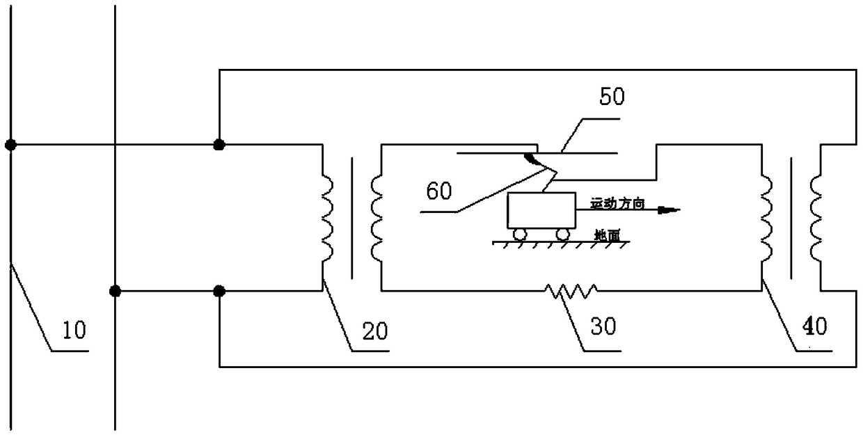
[0017] An embodiment of the present invention provides a pantograph-catenary arc detection method based on a train power supply system. like figure 1 As shown, the power supply system may include: a grid 10 , a step-up transformer 20 , a current limiting resistor 30 , a step-down transformer 40 , catenary conductors 50 , and a discharge circuit formed by a pantograph 60 .
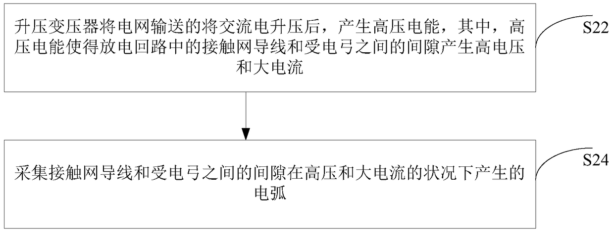
[0018] like figure 2 As shown, the method may include the following steps:
[0019] In step S22, the step-up transformer boosts the alternating current delivered by the grid to generate high-voltage electric energy, wherein the high-voltage electric energy causes the gap between the catenary wire and the pantograph in the discharge circuit to generate high voltage and large current.
[0020] Specifically, in this solution, the above-mentioned step-up transformer can transmit the high-voltage electric energy after the above-mentioned boost to the discharge circuit, that is, the step-up transformer 20, the...
Embodiment 2
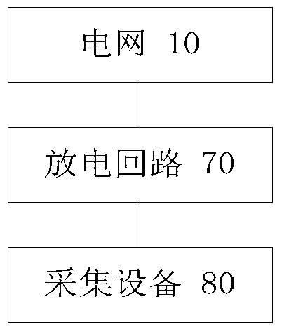
[0045] An embodiment of the present invention provides a pantograph-catenary arc detection system based on a train power supply system. like image 3 As shown, the system can include:
[0046] The grid 10 is used to transmit electric energy.
[0047] The discharge circuit 70 includes: a step-up transformer 20, a current-limiting resistor 30, a catenary wire 50, and a pantograph 60, wherein the step-up transformer 20 is used to boost the alternating current delivered by the power grid to generate high-voltage electric energy, wherein, The high-voltage electric energy makes the gap between the catenary conductor 50 and the pantograph 60 in the discharge circuit generate high voltage and large current.
[0048] The collection device 80 is used to collect the arc generated by the gap between the catenary wire and the pantograph under the condition of high voltage and high current.
[0049] Specifically, the above-mentioned step-up transformer can deliver the above-mentioned boo...
PUM
Abstract
The invention discloses a pantograph-catenary arc detection method and system based on a train power supply system. Among them, the pantograph-catenary arc detection method based on the train power supply system includes: the step-up transformer boosts the alternating current delivered by the power grid to generate high-voltage electric energy, wherein the high-voltage electric energy makes the contact between the catenary wire and the pantograph in the discharge circuit The gap between the catenary wire and the pantograph produces high voltage and high current; collect the arc generated by the gap between the catenary wire and the pantograph under the condition of high voltage and high current, so as to solve the method of pantograph-catenary arc simulation test in the prior art. The pantograph-catenary gap generates high voltage and high current, and a high-voltage AC voltage source is used for power supply, resulting in technical problems of high energy consumption.
Description
technical field [0001] The invention relates to the field of trains, in particular to a pantograph-catenary arc detection method and system based on a train power supply system. Background technique [0002] In recent years, with the rapid development of high-speed railways, the principle of obtaining electric energy for high-speed trains is: to obtain electric energy from the catenary through the sliding contact between the catenary wire and the pantograph slide. However, with the increase of train speed, the coupling vibration intensifies during the contact between the catenary and the pantograph, which seriously deteriorates the electrical contact state between the pantograph and the catenary, resulting in the Off-line occurs frequently, and the pantograph-catenary arc generated during off-line causes severe ablation of the catenary wire and pantograph slide, which poses a huge threat to the safety of high-speed railways and has become a technical bottleneck restricting th...
Claims
Application Information
Patent Timeline
Application Date:The date an application was filed.
Publication Date:The date a patent or application was officially published.
First Publication Date:The earliest publication date of a patent with the same application number.
Issue Date:Publication date of the patent grant document.
PCT Entry Date:The Entry date of PCT National Phase.
Estimated Expiry Date:The statutory expiry date of a patent right according to the Patent Law, and it is the longest term of protection that the patent right can achieve without the termination of the patent right due to other reasons(Term extension factor has been taken into account ).
Invalid Date:Actual expiry date is based on effective date or publication date of legal transaction data of invalid patent.

