A magnetic fluid energy-saving high-gradient magnetic separator for mineral processing

A high-gradient magnetic separator, magnetic fluid technology, applied in high-gradient magnetic separation, high-gradient magnetic separator, cleaning method using liquid, etc., can solve the problem of high power consumption, improve the complexity and Manufacturing costs and other issues, to achieve the effect of solving large energy consumption and simplifying complex structures

Active Publication Date: 2020-06-09
江苏众鑫磁电有限公司
View PDF11 Cites 0 Cited by
  • Summary
  • Abstract
  • Description
  • Claims
  • Application Information

AI Technical Summary

Problems solved by technology

The high-gradient magnetic separators in the prior art mostly use electromagnetic coils to generate the magnetic field, which has the advantages of convenient control and high magnetic field strength, which can reach more than 1.5T, and the magnetic field strength can be adjusted by adjusting the current. The disadvantages are also obvious. Because the electromagnetic coil is used, it needs a large current when generating a magnetic field, and its power consumption is huge. It is a famous "electric tiger". In the field of mineral magnetic separation, not all magnetic separation processes are It is necessary to use a magnetic field above 1.5T for magnetic separation. Therefore, in many rough or weak magnetic separation occasions, the use of electromagnetic coil type high gradient magnetic separator is often "overkill".
Moreover, when the coil is energized to generate a magnetic field, it will also generate huge heat due to eddy current effects and other reasons. The machine must control the heat to operate normally. Therefore, high-gradient magnetic separators that use electromagnetic coil magnetic separation need to be equipped with a set of complex oil Cold or water-cooled circulation system, which further increases the complexity and manufacturing cost of HGMS

Method used


Image

  • A magnetic fluid energy-saving high-gradient magnetic separator for mineral processing
  • A magnetic fluid energy-saving high-gradient magnetic separator for mineral processing
  • A magnetic fluid energy-saving high-gradient magnetic separator for mineral processing

Examples


Embodiment 1

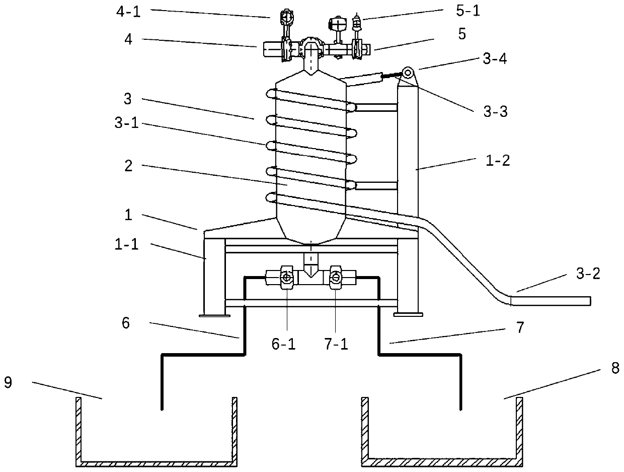
[0036] Refer to attached figure 1 A low-power and energy-saving high-gradient magnetic separator for mineral processing, including a frame 1, a magnetic separation part 2, a magnetic system 3, a pipeline system, and a collection part; the frame 1 includes a lower base 1-1 and an upper support frame 1 -2.

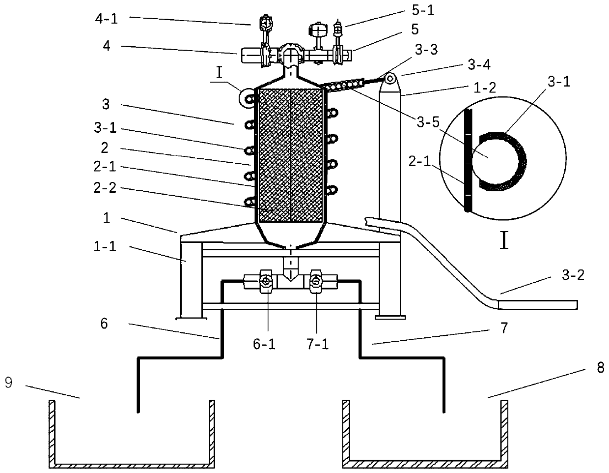
[0037] The magnetic separation part 2 is installed on the lower base 1-1, and the magnetic system 3 is fixedly installed on the outside of the magnetic separation part 2 through the upper support frame 1-2; the magnetic separation part 2 is a cavity structure with a hollow inside and has a magnetic separation cavity 2-1, which is made of magnetically conductive or paramagnetic materials, such as magnetically conductive stainless steel; a magnetic separation medium 2-2 is arranged in the magnetic separation chamber of the magnetic separation part 2, and the magnetic separation medium 2-2 is teeth filled at intervals Plate media, spaced-packed round bar media, tightly-packed ...

Embodiment 2

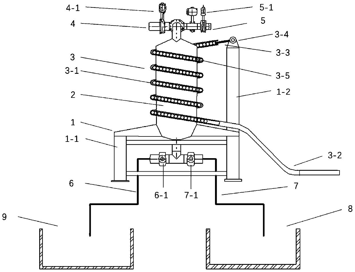
[0051] Another low-power and energy-saving high-gradient magnetic separator for ore dressing using ferrofluid, see attached Figure 7 On the basis of embodiment 1, the collection tray 3-2, collection tank 3-2-1, traction rope 3-3, lifting device 3-4 and permanent magnet 3-5 in the original embodiment 1 are replaced by magnetic Fluid pipeline 3-6, circulating pump 3-7, discharge valve 3-8, magnetic fluid reservoir 3-9 and polarized coil 3-10 (optional), the spiral pipeline 3 in the original embodiment 1 -1 is changed to a closed pipe, the cross-section of which is preferably rectangular, made of inorganic non-metallic materials, such as glass and other materials. The magnetic fluid pipeline 3-6 is connected with the spiral pipeline 3-1, and the circulating pump 3-7, the discharge valve 3-8, and the polarizing coil 3-10 (optional) are all installed on the magnetic fluid pipeline 3-6 , and the magnetic fluid reservoir 3-9 communicates with the magnetic fluid pipeline 3-6 at the ...

Embodiment 3

[0064] See attached Figure 8 , a kind of enhanced low power consumption energy-saving type high gradient magnetic separator, it has increased a helical pipeline 3-1 and its matching collection plate 3-2, traction rope 3-3, The hoisting device 3-4 and the permanent magnet 3-5 adopt a double-layer spiral pipeline, the two spiral pipelines have opposite directions of rotation, and the permanent magnets 3-5 in the two spiral pipelines 3-1 have opposite polarity sequences at the head and tail. So that the magnetic system 3 can generate magnetic induction lines superimposed in the same direction in the magnetic separation cavity of the magnetic separation part 2, and is used to increase the intensity of the magnetic field formed in the magnetic separation cavity of the magnetic separation part 2, its working principle, control method and implementation Same as in Example 1.

[0065] Simultaneously, also can try on the basis of embodiment 2 to increase a helical pipeline 3-1 and it...


PUM


Abstract

The invention provides a magnetic fluid type energy-saving high-gradient magnetic separator for mineral processing. The magnetic fluid type energy-saving high-gradient magnetic separator comprises a frame, a magnetic separation part, a magnetic system, a pipe system and a collecting part. The frame comprises a lower base and an upper support frame. The magnetic separation part is mounted on the lower base, and the magnetic system is fixedly mounted outside of the magnetic separation part through the upper support frame. The magnetic separation part is an internally hollow cavity structure having a magnetic separation chamber wall, the magnetic system includes a magnetic fluid system and a spiral pipeline, and the magnetic fluid system includes a magnetic fluid pipe, a circulation pump, a venting valve, and a magnetic fluid reservoir. The spiral pipeline is closely arranged outside the magnetic separation part and is in a close spiral rise arrangement. The magnetic fluid pipe communicates with the spiral pipeline, both the circulation pump and the venting valve are installed on the magnetic fluid pipe, and the magnetic fluid reservoir communicates with the magnetic fluid pipe. Due to the adoption of the magnetic fluid structure, a permanent magnet material is applied to the high-gradient magnetic separator for magnetic separation, the problems of the large energy consumption ofa high-gradient magnetic separator and the complicated structure of a cooling system in the prior art are solved, and the costs of manufacturing, use and maintenance are reduced.

Description

technical field [0001] The invention relates to a high-gradient magnetic separator, in particular to a low-power and energy-saving high-gradient magnetic separator for magnetic separation from fluid ore pulp. Background technique [0002] In the history of human mineral extraction, magnetic field has been used for magnetic separation of minerals for more than 100 years. Due to the constraints of the development of basic science such as theory and materials, the initial magnetic separator has not been widely used. Since the use of electromagnets to generate magnetic fields in 1855, the theory and practice of magnetic separators have become more and more perfect. Various types of industrial magnetic separation equipment have emerged in the industry, and magnetic separation has been widely used in iron ore beneficiation. application. After the 1960s, with the continuous development of material science, the magnetic field strength of permanent magnet materials became stronger a...

Claims


Application Information

Patent Timeline
Patent Type & Authority Patents(China)
IPC IPC(8): B03C1/033B03C1/031B08B3/02
CPCB03C1/002B03C1/031B03C1/0332B08B3/02
Inventor 刘新珍
Owner 江苏众鑫磁电有限公司
Why Eureka
Try Eureka