
A delay multi-carrier modulation and demodulation method

A technology of multi-carrier modulation and demodulation method, which is applied in the field of time-delay multi-carrier modulation and demodulation, and can solve problems such as increasing system complexity, inter-wavelet interference, and inability to completely avoid smearing

Active Publication Date: 2018-03-23
DALIAN MARITIME UNIVERSITY
View PDF4 Cites 0 Cited by
  • Summary
  • Abstract
  • Description
  • Claims
  • Application Information

AI Technical Summary

Problems solved by technology

The transmission waveform of this structure has much higher transmission efficiency and other excellent characteristics than the existing structure waveform; however, there are three disadvantages in this modulation and demodulation method: First, there are ill-conditioned problems in the equation system in some cases , Second, in the communication system, after the waveform passes through the channel, it will be deformed and expanded forward and backward (hereinafter referred to as the extended part as front and rear smear or collectively referred to as smear), even through equalization, in most cases, the generation of smear cannot be completely avoided , due to the time shift between wavelets, the smear is extended to other wavelets, resulting in interference between wavelets, and it is impossible to separate the time gap between two symbols as in traditional digital communication modulation. Or add a cyclic prefix to each wavelet like OFDM. Third, its demodulation needs to go through multiple coherent operations to obtain a linear equation set. Only by solving this set of equations can the demodulation be completed. The whole process is quite complicated. ; Although, in the patent "Additive Waveform Preprocessing Method in Digital Communication Modulation" (Application No.: 200710099731.6), it is proposed to reduce trailing and ill-conditionedness by adding additional waves, which solves the problem between wavelets to a considerable extent. Interfering and pathological problems
But the process of adding additional waves is a rather time-consuming process, and at the same time further increases the complexity of the system

Method used


Image

  • A delay multi-carrier modulation and demodulation method
  • A delay multi-carrier modulation and demodulation method
  • A delay multi-carrier modulation and demodulation method

Examples


Embodiment Construction

[0117] In order to make the object, technical solution and advantages of the present invention clearer, the present invention will be further described in detail below in conjunction with the accompanying drawings.

[0118] The invention provides a delay multi-carrier modulation and demodulation method, in particular, it provides multiple demodulation methods: (1) a positive triangular equation group method, (2) an inverse triangular equation group method, and (3) a priority method. Compared with "A Time-Frequency Mixed Multi-Carrier Modulation Method", since the forward and inverse triangular equations are positive definite, it avoids the ill-conditionedness of the equations and saves the coherent operation with high complexity. The optimal solution is selected from the comparison of the solutions of the positive and negative triangular equations to further improve the accuracy of the demodulation.

[0119] Specifically include: a modulation and demodulation method correspond...


PUM


Abstract

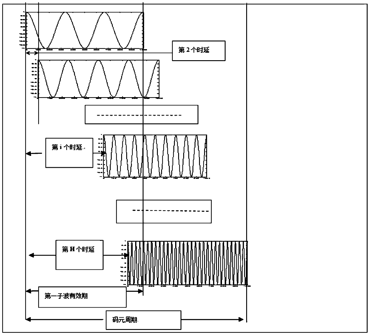
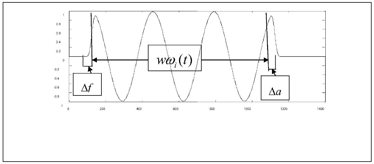
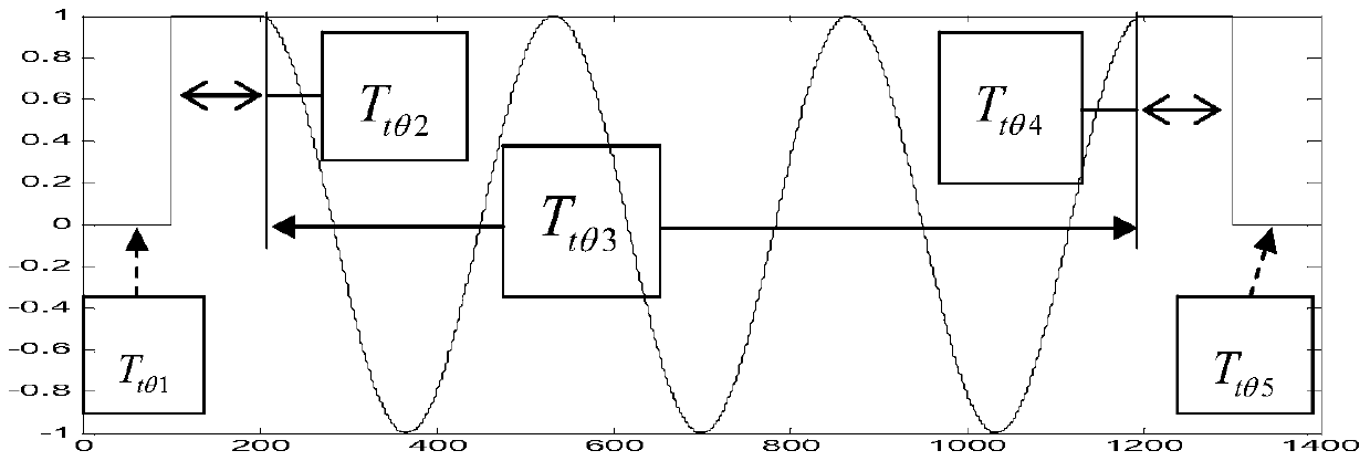
The invention discloses a time-delay multi-carriers modulation and demodulation method. The code element waveform structure is composed of H cosine wavelets, all wavelets have different time delays sequentially, and various wavelets are linearly superposed to form a non-orthogonal composite wave code element waveform; the wavelets are amplitude-variable basic wavelets, and the basic wavelets are standard cosine waves with amplitude at 1 constantly. Meanwhile, the basic wavelets of a transmission end are transmitted finishing basic wavelets with a trailing area 0 and a trailing area 1 added at two ends of the standard cosine waves, and a receiving end is partially balanced to obtain received finishing basic wavelets with trailing to form non-orthogonal composite waves. The modulation adopts three methods including (1) an equilateral-triangle equation set method formed by an equilateral-triangle coefficient matrix; (2) an inverted-triangle equation set method formed by an inverted-triangle coefficient matrix; (3) an optimization method. The time-delay multi-carriers modulation and demodulation method reserves the advantages of high efficiency of a time-frequency mixing multi-carriers modulation method and reduces complexity as well as error bit rate.

Description

technical field [0001] The present invention relates to a carrier modulation technology, in particular to a time-delay multi-carrier modulation and demodulation method (referred to as TDMC—A Time-Delay Multi-Carriers Modulation and Demodulation), which belongs to the multi-carrier modulation technology in digital communication field. Background technique [0002] The waveforms transmitted in the digital communication system are organized according to equal time intervals, and each time interval is a period (hereinafter denoted by T) and the signal in between is called a symbol. All symbol waveforms have a common basic waveform, and binary information is loaded onto the basic waveform through modulation to form a series of different symbol waveforms. The inventor once proposed a symbol waveform with a special structure and a corresponding modulation and demodulation method in the patent "Multi-carrier Modulation Method with Time-Frequency Mixing" (application number: 2008101...

Claims


Application Information

Patent Timeline
Patent Type & Authority Patents(China)
IPC IPC(8): H04L27/26
CPCH04L27/2601H04L27/2607
Inventor 梁德群
Owner DALIAN MARITIME UNIVERSITY
Learn More