Turning device for catapult power device

A technology of a power device and a flip device, which is applied to the launch device and other directions, can solve the problems that the ejection power device cannot be used and stopped at any time, and the vertical lifting requirements of the ejection power device cannot be realized.

Active Publication Date: 2015-05-20
BEIJING INST OF SPACE LAUNCH TECH +1
View PDF5 Cites 2 Cited by
  • Summary
  • Abstract
  • Description
  • Claims
  • Application Information

AI Technical Summary

Problems solved by technology

At present, the loading method of installing the ejection power device of the launch tube on the bracket is mainly horizontal loading of the trolley, which cannot meet

Method used


Image

  • Turning device for catapult power device
  • Turning device for catapult power device

Examples


Embodiment Construction

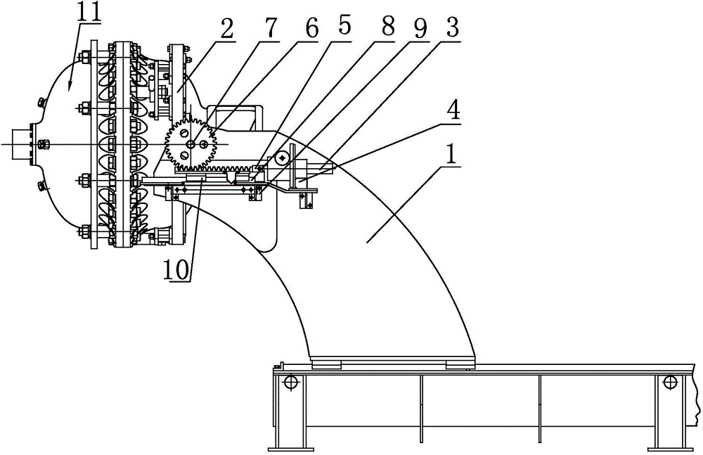
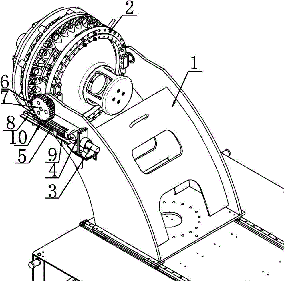
[0015] Such as figure 1 , figure 2 As shown, the flipping device for the ejection power device of the present invention includes a screw jack 3 installed on one side of the sliding bracket 1 through a first bracket 4, a rack 5 welded to the output end of the screw of the screw jack 3, and meshed with the rack 5. The gear 6 and the rack 5 are arranged on one side of the sliding bracket 1 through the support seat, the bottom of the rack 5 is equipped with a guide rail 8 parallel to the rack 5, and the guide rail 8 is fixed on one side of the sliding bracket 1 through the second bracket 9 On the contact surface of the rack 5 and the guide rail 8, a slider 10 is welded, the rack 5 can drive the slider 10 to move back and forth along the guide rail 8, the gear shaft 7 is sleeved on the gear 6, and the gear 6 drives the gear through a flat key The shaft 7 rotates synchronously. One end of the gear shaft 7 passes through the sliding bracket 1 and is screwed to the mounting flange 2...


PUM


Abstract

The invention discloses a turning device for a catapult power device, and relates to the turning device which is used for conducting vertical lifting and horizontal filling on the catapult power device. The invention aims at providing the turning device which is simple in structure, safe and convenient, and simple and convenient in operation. The turning device for the catapult power device comprises a spiral elevator which is arranged on one side of a sliding support through a first support, a rack which is fixedly connected with the output end of a screw of the spiral elevator, and a gear wheel which is meshed with the rack; the rack is fixed at one side of the sliding support through a supporting seat, the gear wheel is connected with a gear wheel shaft which rotates synchronously with the gear wheel in a sleeving mode, and one end of the gear wheel shaft penetrates through the sliding support and is in rigid connection with a mounting flange. By means of the turning device for the catapult power device, the requirements of the vertical lifting and the horizontal filling for the catapult power device are met, 90 degrees turnover of the catapult power device can be achieved conveniently, and the catapult power device can be fastened at any position in the turnover process.

Description

technical field [0001] The invention relates to an auxiliary device, in particular to an overturning device for vertical hoisting and horizontal loading of ejection power devices. Background technique [0002] With the advancement of science and technology, missiles, as a kind of flying weapon that can designate attack targets or track target movements, have achieved rapid development. The power plant is used as a gas generating device for cold ejection of missiles, and it has a high installation index. At present, the loading method of installing the ejection power device of the launch tube on the bracket is mainly horizontal loading of the trolley, which cannot meet the vertical hoisting requirements of the ejection power device, and cannot realize the instant stop of the ejection power device during the hoisting process. Contents of the invention [0003] The technical problem to be solved by the present invention is to provide a flipping device for ejection power devi...

Claims


Application Information

Patent Timeline
IPC IPC(8): F41F1/00
Inventor 毛成元郑国梁贾学军张杰刘广娟
Owner BEIJING INST OF SPACE LAUNCH TECH
Why Eureka
Try Eureka