soil sampler

A technology of sampler and soil, which is applied in the direction of sampling device, etc., can solve the problem of sampling soil pushing out, and achieve the effect of avoiding secondary sampling, ensuring the plugging effect and improving the success rate of sampling

Inactive Publication Date: 2018-07-20
平顶山市质量技术监督检验测试中心
View PDF13 Cites 1 Cited by
  • Summary
  • Abstract
  • Description
  • Claims
  • Application Information

AI Technical Summary

Problems solved by technology

[0005] The present invention provides a soil sampler to solve the problem that the sampling port on the sampling head of the soil sampler in the prior art is arranged at the bottom of the sampling head so that the sampling inner cavity is easily blocked when the sealing structure on the inner rod re-blocks the sampling port. Technical Issues in the Rollout of Sampling Soil

Method used


Image

  • soil sampler
  • soil sampler
  • soil sampler

Examples


Embodiment Construction

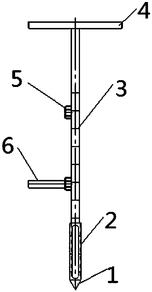
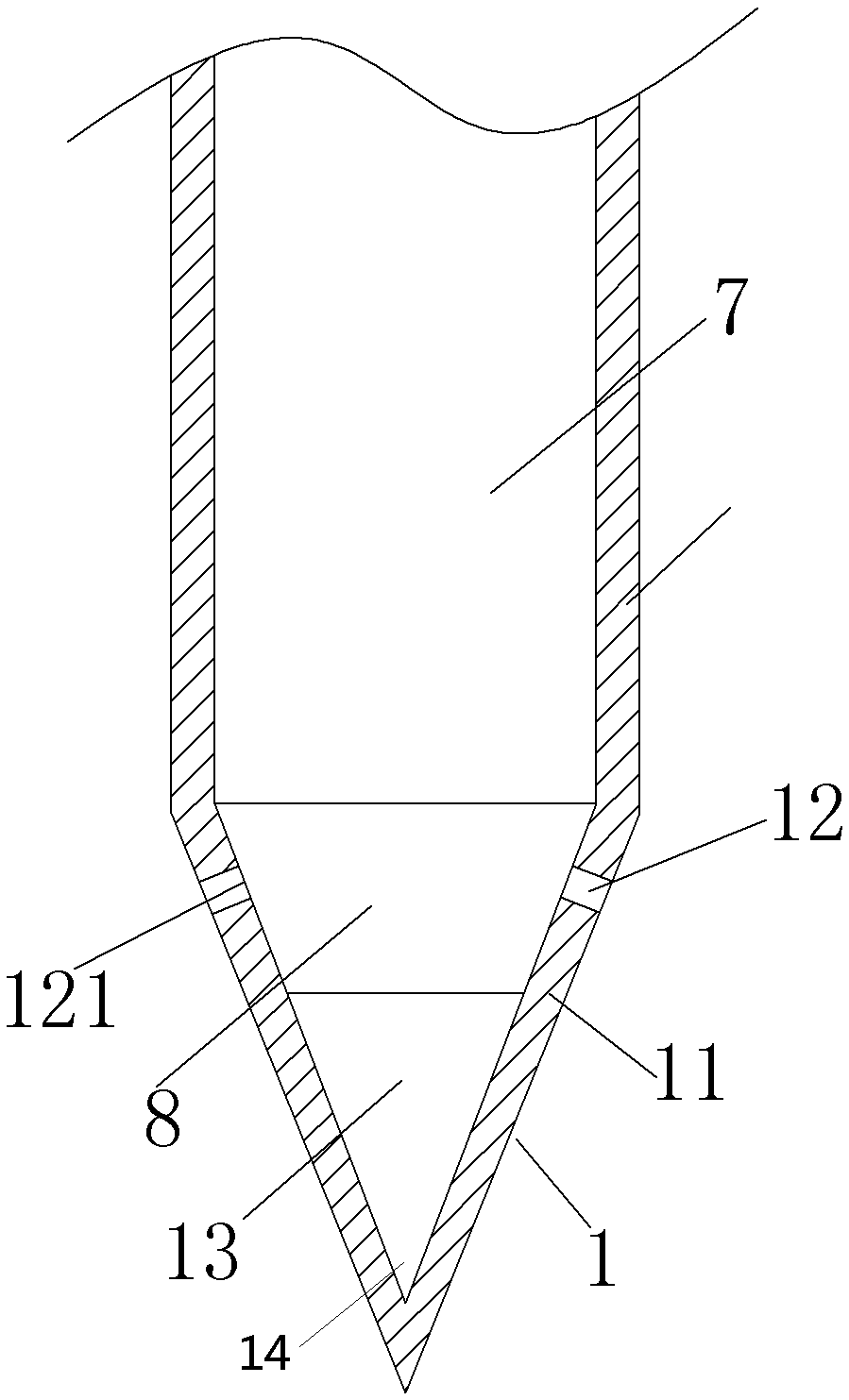
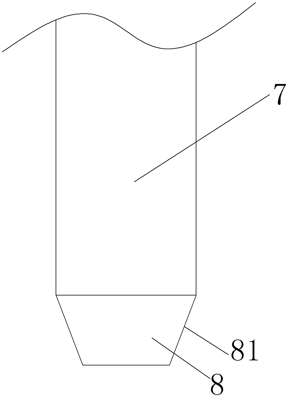
[0026] Such as Figure 1 to Figure 3 Shown, a kind of embodiment of soil sampler, the soil sampler in this embodiment comprises outer tube 2, and outer tube 2 bottom is provided with hollow sampling head 1, and the bottom of sampling head is sealing structure, and sampling head 1 has for The circumferential side wall 11 of the hollow cavity 13 is formed. The circumferential side wall 11 of the sampling head 1 is a conical side wall with a large top and a small bottom. On the circumferential side wall 11 of the sampling head 1, there is a The sampling holes 12 communicated with the cavity 13, the sampling holes 12 are evenly distributed around the sampling head circumferential direction, and the sampling holes 12 have an inner orifice 121 extending to the inner wall surface of the circumferential side wall 11 facing the hollow inner cavity 13, the inner orifice 121 is higher than the bottom of the hollow inner cavity 13 in the vertical direction, where the bottom of the hollow ...


PUM


Abstract

The invention provides a soil sampling device. The soil sampling device comprises an outer pipe, wherein a hollow sampling head is arranged at the lower part of the outer pipe; the sampling head is provided with a peripheral side wall for forming a hollow inner cavity; the sampling head is provided with a sampling hole communicated with the hollow inner cavity; an inner rod which can move back and forth in an up-down direction is arranged in the outer pipe; the inner rod is provided with a blocking structure for correspondingly opening and blocking the sampling hole when the inner rod moves up and down; the sampling hole is formed in the peripheral side wall; the sampling hole is provided with an inner hole which extends to an inner wall surface toward the hollow inner cavity of the peripheral side wall; the inner hole is higher than the bottom of the hollow inner cavity in the up-down direction; and the blocking structure is located in the hollow inner cavity and is used for opening and blocking the sampling hole through controlling the opening and closing of the inner hole when the inner rod moves up and down. Soil entering the hollow inner cavity falls into the bottom of the hollow inner cavity, and the soil is not pushed out of the hollow inner cavity by the blocking structure on the inner rod, so that the sampling success rate is improved.

Description

technical field [0001] The invention relates to a soil sampler. Background technique [0002] The texture and composition of soil have an important impact on agriculture, industry and other fields, so it is necessary to sample and analyze the soil, which requires the use of soil samplers. Conventional soil samplers take columnar samples through sampling tubes so that soil layers can be analyzed. However, this conventional soil sampler collects all soil layers. On the one hand, due to the binding force between the soil layers, a large pressure is required to insert the sampling tube into the soil, which is very laborious. On the other hand, it cannot be set separately. Soil at depth, the sampling efficiency is low. [0003] A soil sampler is disclosed in the Chinese utility model patent with the authorized announcement number CN203606178U, which includes an outer tube and an inner rod movable in the outer tube along the up and down direction. The outer tube is provided with...

Claims


Application Information

Patent Timeline
Patent Type & Authority Patents(China)
IPC IPC(8): G01N1/08
Inventor 刘万兵郭红梅郭志勇秦志阳杨光周刚伟孙喜闯
Owner 平顶山市质量技术监督检验测试中心
Why Eureka
Try Eureka