A fuze isolation mechanism

A technology of isolation mechanism and fuze, applied in fuze, weapon accessories, offensive equipment and other directions, can solve the problems of poor recoverability and low safety factor, and achieve the effect of low cost, high safety and reliable recovery

Inactive Publication Date: 2016-06-22
湖北三江航天红林探控有限公司
View PDF6 Cites 2 Cited by
  • Summary
  • Abstract
  • Description
  • Claims
  • Application Information

AI Technical Summary

Problems solved by technology

[0007] The invention provides a fuze isolation mechanism, the purpose of which is to unlock and lock the two partitions through the driving force and compression force generated by the successive power-on and power-off of two vertically placed springs, thereby realizing reliable isolation between the release isolation state and the isolation state. Conversion, which solves the problems of poor recoverability and low safety factor of the existing fuze isolation mechanism

Method used


Image

  • A fuze isolation mechanism
  • A fuze isolation mechanism
  • A fuze isolation mechanism

Examples


specific Embodiment 1

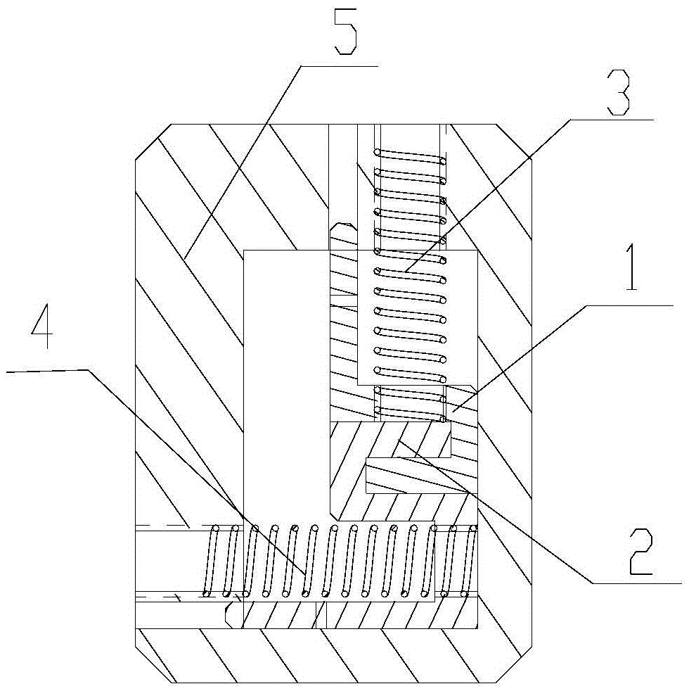
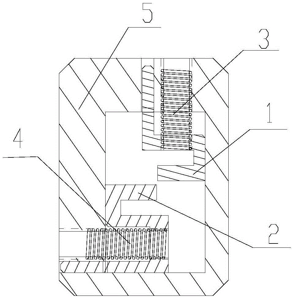
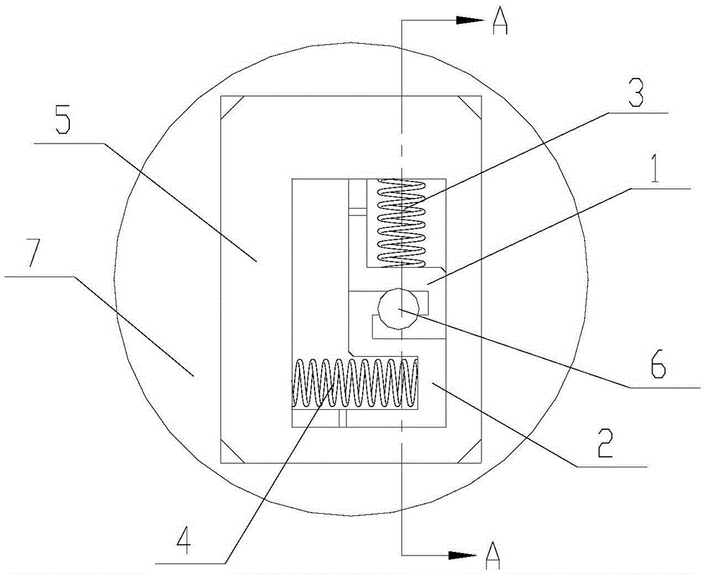
[0020] Such as figure 1 As shown, this example includes a first U-shaped partition 1 , a second U-shaped partition 2 , a first spring 3 , a second spring 4 and a frame 5 . The frame 5 is equipped with a first spring 3 , a first U-shaped partition 1 , a second U-shaped partition 2 and a second spring 4 .

[0021] Both the first spring 3 and the second spring 4 are made of high-temperature shortened two-way CuZnAl shape memory alloy material. The first spring 3 is placed vertically, and its upper and lower ends are respectively threaded and fixed in the corresponding threaded holes on the upper surface of the frame 5 and the first U-shaped partition 1; the second spring 4 is placed horizontally, and its left and right ends are threaded respectively. It is fixed in the corresponding threaded holes on the side of the frame 5 and the second U-shaped partition 2. When the first spring 3 and the second spring 4 are installed on the first U-shaped partition 1 and the second U-shaped...

specific Embodiment 2

[0028]In this embodiment, except that when the first spring 3 and the second spring 4 are installed on the first U-shaped partition 1 and the second U-shaped partition 2 respectively, the compression amount is 10%, and the first spring 3 and the installation direction of the second spring 4 are perpendicular to each other. And the positions corresponding to the first U-shaped partition 1 and the second U-shaped partition 2 on the frame 5 are respectively provided with longitudinal and transverse guide grooves, the first U-shaped partition 1 and the second U-shaped partition 2 All stretch into outside 3mm in the guide groove of frame 5. Other compositions and connections are the same as in Example 1.


PUM


Abstract

The invention discloses a fuze isolation mechanism which comprises a frame, and a first U-shaped separator, a second U-shaped separator, a first spring and a second spring which are arranged in the frame, wherein the two springs are two-way shape memory alloy materials; the first spring is longitudinally connected with the first U-shaped separator; the second spring is transversely connected with the second U-shaped separator; notches of the two separators are opposite to each other and are embedded into a whole in a dislocated mode under the action of the compressing force of the two springs, so that fuze isolation is realized; after the second spring and the first spring are sequentially electrified, the second U-shaped separator is pulled to transversely move by virtue of the retractive force generated by the second spring, and the first U-shaped separator is pulled to longitudinally move by virtue of the retractive force generated by the first spring, so that fuze isolation is released; and after the power of the first spring and the second spring is sequentially cut off, the first U-shaped separator and the second U-shaped separator are sequentially reset to the fuze isolation state. According to the fuze isolation mechanism disclosed by the invention, reliable switching between the isolation release state and the isolation state is realized, and the problem that the conventional fuze isolation mechanism is low in restorability and low in safety coefficient is solved.

Description

technical field [0001] The invention belongs to the technical field of fuzes, and in particular relates to a fuze isolation mechanism. Background technique [0002] The function of the isolation mechanism is to isolate the sensitive pyrotechnic components in the detonation sequence from the next-level pyrotechnic components at ordinary times, so as to ensure that the fuze does not ignite when the pyrotechnic products accidentally act in advance, so as to avoid the premature explosion of the ammunition and endanger personnel and equipment. Safety. When the weapon moves to a certain safe distance after firing, the isolation mechanism should be able to release the isolation so that the detonation sequence can be conducted. [0003] At present, the basic movement forms of the isolation mechanism of the fuze include sliding and rotation, and the components driving the movement of the isolation mechanism include stepping motors, gunpowder actuators, etc. Due to the complexity of...

Claims


Application Information

Patent Timeline
Patent Type & Authority Patents(China)
IPC IPC(8): F42C15/00
Inventor 李响梅江涛陈亮
Owner 湖北三江航天红林探控有限公司
Why Eureka
Try Eureka