Method for strengthening side wall of debris flow drainage groove with stone masonry structure

A drainage channel and debris flow technology, applied in water conservancy projects, artificial waterways, embankments, etc., can solve the problems of difficulty in large-scale promotion and application, insufficient construction convenience, and insufficient utilization, so as to ensure normal performance and improve resistance to debris flow impact. The effect of performance and engineering cost saving

Inactive Publication Date: 2011-07-27
INST OF MOUNTAIN HAZARDS & ENVIRONMENT CHINESE ACADEMY OF SCI
View PDF0 Cites 1 Cited by
  • Summary
  • Abstract
  • Description
  • Claims
  • Application Information

AI Technical Summary

Problems solved by technology

[0004] In order to prevent the foundation damage of the side wall of the mud-rock flow drainage channel of the masonry structure, the railway department, water conservancy department, etc. adopt an all-concrete structure or a reinforced concrete structure for the engineering structure of the side wall of the mud-rock flow drainage channel that is particularly important, but the cost of these measures Too high, or due to factors such as insufficient use of local building materials and insufficient construction convenience, it is difficult to promote and apply in a large area

Method used


Image

  • Method for strengthening side wall of debris flow drainage groove with stone masonry structure
  • Method for strengthening side wall of debris flow drainage groove with stone masonry structure
  • Method for strengthening side wall of debris flow drainage groove with stone masonry structure

Examples


Embodiment 1

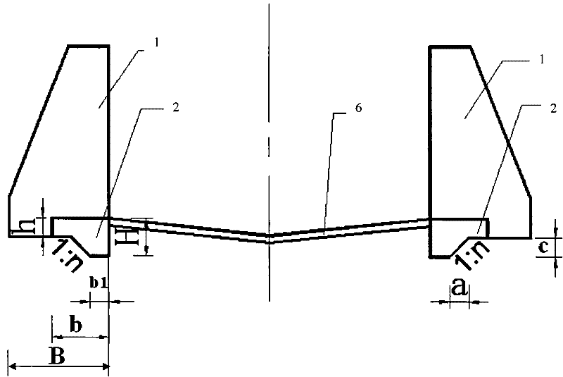
[0034] like figure 1 , figure 2 , image 3 shown. For a watershed area of ​​1.2km 2 , The slope of the accumulation fan is 15%. On the debris flow accumulation fan, build a 150m-long fully-lined debris flow drainage channel, including the fully lined bottom plate 6 and the side walls 1 of the drainage channel on both sides, and use the L-shaped beam foundation 2 to guide the debris flow of the masonry structure The groove side wall 1 is reinforced. The L-shaped beam foundation 2 is firstly constructed, and then the side wall 1 of the drainage channel of the mortar masonry structure is constructed, and then the fully lined bottom plate 6 is constructed.

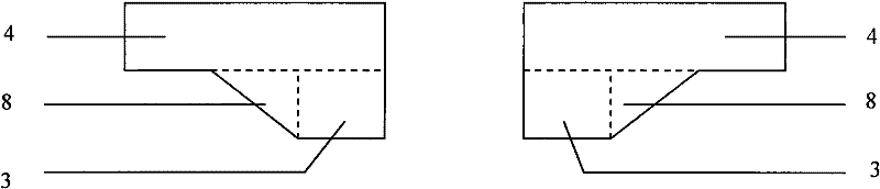
[0035]Both sides are provided with an L-shaped beam foundation 2 to reinforce the foundation of the side wall 1 of the guide groove, and the L-shaped beam foundation 2 is connected with the side wall 1 of the guide groove to form a whole. The L-shaped beam foundation 2 includes a toe 3 and a thin plate 4, the toe 3 is l...

Embodiment 2

[0038] like figure 1 , Figure 4 , Figure 5 shown. The same as the first embodiment will not be repeated, the difference is: the basin area is 26.0km 2 , The slope of the accumulation fan is 5%. On the debris flow accumulation fan, build a 600m-long soft foundation energy-dissipating debris flow drainage channel, including the side walls 1 of the drainage channel on both sides and the anti-scour tooth sill 7 placed in between, and adopt the L-shaped beam foundation with 2 pairs of slurry The side wall 1 of the debris flow drainage channel of the masonry structure is reinforced.

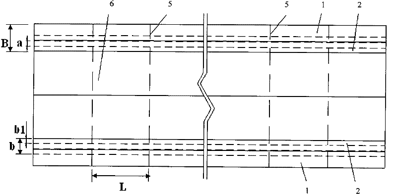
[0039] There are 19 settlement joints 5, and the distance L between the settlement joints 5 is 30.0m. The thickness H of the toe foot 3 plus the thin plate 4 is 3.0m, the thickness h of the thin plate 4 is 1.0m, the foundation width b of the L-shaped beam foundation 2 is 4.0m, the width b1 of the toe foot 3 is 1.0m, and the side wall of the drainage channel 1 The foundation width B is 4.5m. Th...

Embodiment 3

[0042] like figure 1 , Image 6 shown. The same as the first embodiment will not be repeated, the difference is: the full-lined debris flow drainage channel is a slanted wall structure, the right side of the toe foot 3 and the right side of the thin plate 4 and the left side wall of the drainage channel 1 The fold line on the inner side of the toe pin 3 and the left side of the thin plate 4 are continuously connected to the inner side of the side wall 1 of the right row of guide grooves. The foundation width b of the L-shaped beam foundation 2 is equal to the foundation width B of the side wall 1 of the row channel, both of which are 1.5m. The top surface of the thin plate 4 is on the same surface as the bottom surface of the side wall 1 of the guide groove.


PUM


Abstract

The invention discloses a method for strengthening the side wall of a debris flow drainage groove with stone masonry structure. In the method, an L-shaped beam foundation is arranged at the bottom of the side wall of the drainage groove to strengthen the foundation of the side wall of the drainage groove; the L-shaped beam foundation is connected with the side wall of the drainage groove and comprises a toe foot and a thin plate, wherein the toe foot is positioned below the thin plate, the top surface of the toe foot is overlapped with the part of the bottom surface of the thin plate, one side surface of the toe foot and one side surface of the thin plate are in the same plane, and the two side surfaces are successively connected with the internal side surface of the side wall of the drainage groove. Compared with the prior art, by fully using the advantages of erosion prevention, differential settlement resistance and the like of the L-shaped beam foundation, the invention improves the debris flow resisting performance and the differential settlement resisting integrity of the side wall by sections, prevents the safety of the whole drainage groove from being endangered by the local damage of the side wall, fully ensures the normal use of the drainage function of the debris flow drainage groove and saves the engineering cost and the engineering maintenance cost.

Description

technical field [0001] The invention relates to a mud-rock flow prevention technology, in particular to a reinforcement method for a side wall foundation of a mud-rock flow drainage channel with a masonry structure. Background technique [0002] Debris flow disaster is one of the main types of geological disasters in my country. With the development of the mountainous area economy and the deepening of the western development, the demand for debris flow engineering control is becoming more and more vigorous. The debris flow drainage channel is a common engineering measure for debris flow engineering control. It has been widely used in the past, and it will also be widely used in debris flow engineering control in the future. . [0003] Due to factors such as cost control, local materials, and construction convenience, the engineering structure of the side wall of the debris flow drainage channel adopts a large number of mortared masonry structures. As strong as the inside o...

Claims


Application Information

Patent Timeline
Patent Type & Authority Patents(China)
IPC IPC(8): E02B5/00E02B3/10E01F7/04
Inventor 陈晓清游勇崔鹏李德基高全
Owner INST OF MOUNTAIN HAZARDS & ENVIRONMENT CHINESE ACADEMY OF SCI
Why Eureka
Try Eureka