Touch locating method and optical touch system

一种触控定位、光学触控的技术,应用在仪器、电数字数据处理、数据处理的输入/输出过程等方向,能够解决不便等问题,达到增加输入功能、有效率触碰输入的效果

Active Publication Date: 2015-06-03
WISTRON CORP
View PDF3 Cites 3 Cited by
  • Summary
  • Abstract
  • Description
  • Claims
  • Application Information

AI Technical Summary

Problems solved by technology

[0002] Existing optical touch systems, whether single-touch or multi-touch, can only determine the position of a single touch point on the touch screen, such as the area where the stylus touches the touch screen. center position
If you need to input the rotation angle information at the same time, you need to input it separately, such as through the keyboard or trackball, which is very inconvenient

Method used


Image

  • Touch locating method and optical touch system
  • Touch locating method and optical touch system
  • Touch locating method and optical touch system

Examples


Embodiment Construction

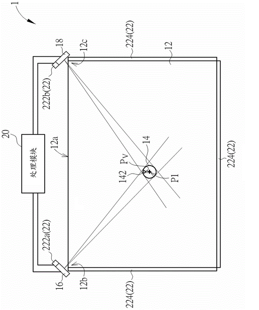
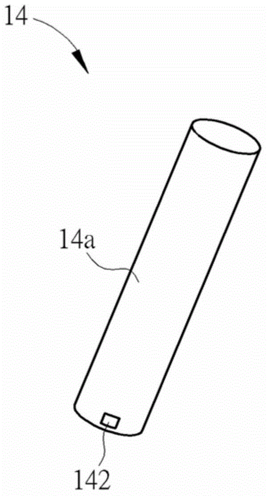
[0034] see figure 1 , which is a schematic diagram of an optical touch system 1 according to an embodiment of the present invention, wherein for convenience of description, some components of the optical touch system 1 are shown exaggeratedly in the figure. The optical touch system 1 includes a touch area 12, an indicator (such as a stylus 14, represented by a circle in figure 1 Middle), a first optical sensor 16 , a second optical sensor 18 , a processing module 20 and a light generating module 22 . In practice, the touch area 12 can be an area defined on the display screen. The stylus 14 is used for performing a touch operation on the touch area 12 . The first optical sensor 16 is disposed at a first corner 12 b of a periphery 12 a of the touch area 12 , and the second optical sensor 18 is disposed at a second corner 12 c of the periphery 12 a of the touch area 12 . The processing module 20 is electrically connected to the first optical sensor 16 and the second optical se...


PUM


Abstract

A locating method for an optical touch system determines a center position of an indication object on a touch area of the optical touch system by an optical location means. The locating method determines a light-emitting position of a light emitter of the indication object on the touch area by receiving indication light emitted from the light emitter by two optical sensors. The locating method determines a touch position and a touch direction according to a relative relationship between the center position and the light-emitting position; therein, the touch position can be regarded as a touch point on the touch area by the indication object, and the touch direction can be regarded as a rotation angle of the indication object relative to the touch area.

Description

technical field [0001] The invention relates to a touch control system, in particular to an optical touch control system and a touch positioning method thereof. Background technique [0002] Existing optical touch systems, whether single-touch or multi-touch, can only determine the position of a single touch point on the touch screen, such as the area where the stylus touches the touch screen. center point position. If it is necessary to input the rotation angle information at the same time, it needs to be input separately, for example, through a keyboard or a trackball, which is very inconvenient. Therefore, there is a need to enhance the input function of the stylus to facilitate the user to input more information at the same time. Contents of the invention [0003] In view of the problems in the prior art, one of the objectives of the present invention is to provide a touch positioning method, which can provide touch position and touch direction positioning functions ...

Claims


Application Information

Patent Timeline
Patent Type & Authority Applications(China)
IPC IPC(8): G06F3/042
CPCG06F3/03545G06F3/04162G06F3/0428
Inventor 魏守德苏上钦
Owner WISTRON CORP
Why Eureka
Try Eureka