
Lamp bulb durability testing device

A test device and durability technology, applied in the field of lighting, can solve problems such as the failure of the light source to work normally, the damage of metal friction, and the inability to guarantee the reliability of the light source lamp head of the lamp.

Inactive Publication Date: 2015-06-10
OCEANKING DONGGUAN LIGHTING TECH +2
View PDF0 Cites 5 Cited by
  • Summary
  • Abstract
  • Description
  • Claims
  • Application Information

AI Technical Summary

Problems solved by technology

[0002] Special lamps are widely used in various industries because of their high safety and reliability. The most important components in lamps are light sources and electrical components, and the devices that maintain the position of the light source and connect the light source with electrical components are lamps. When the lamp holder is connected to the light source, the method is a spiral, and the light source is fixed in the lamp holder by thread rotation. At the same time, the thread in the lamp holder has another function to provide power to the light source, and the thread in the lamp holder It is a metal part. The lamp holder of the light source is also a metal part. It plays the role of fixing the light source and transmitting electric energy. When the two metals are used in a long-term stress environment (such as: vibration, shock environment), the friction between the metals will be damaged, resulting in the light source not working normally. Work
Therefore, the durability of the thread of the light source must be investigated during the design of the lamp, but now there is no such tooling for testing, so the reliability of the lamp head cannot be guaranteed.

Method used


Image

  • Lamp bulb durability testing device
  • Lamp bulb durability testing device
  • Lamp bulb durability testing device

Examples


Embodiment Construction

[0019] The following will clearly and completely describe the technical solutions in the embodiments of the present invention with reference to the drawings in the embodiments of the present invention.

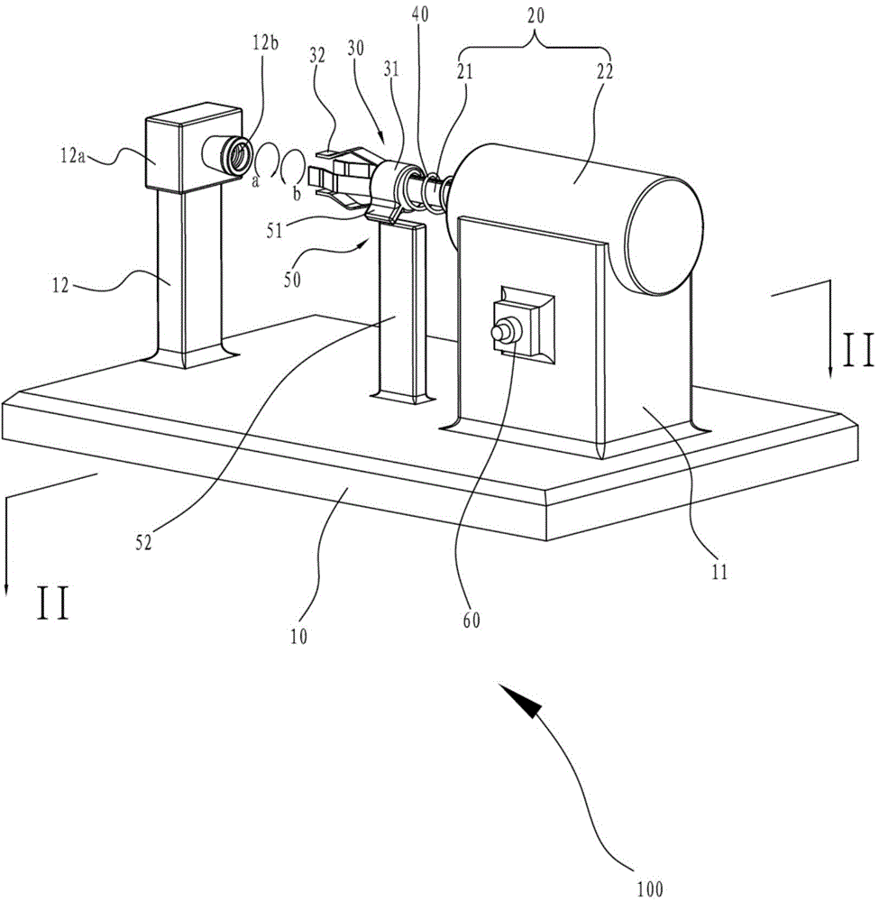
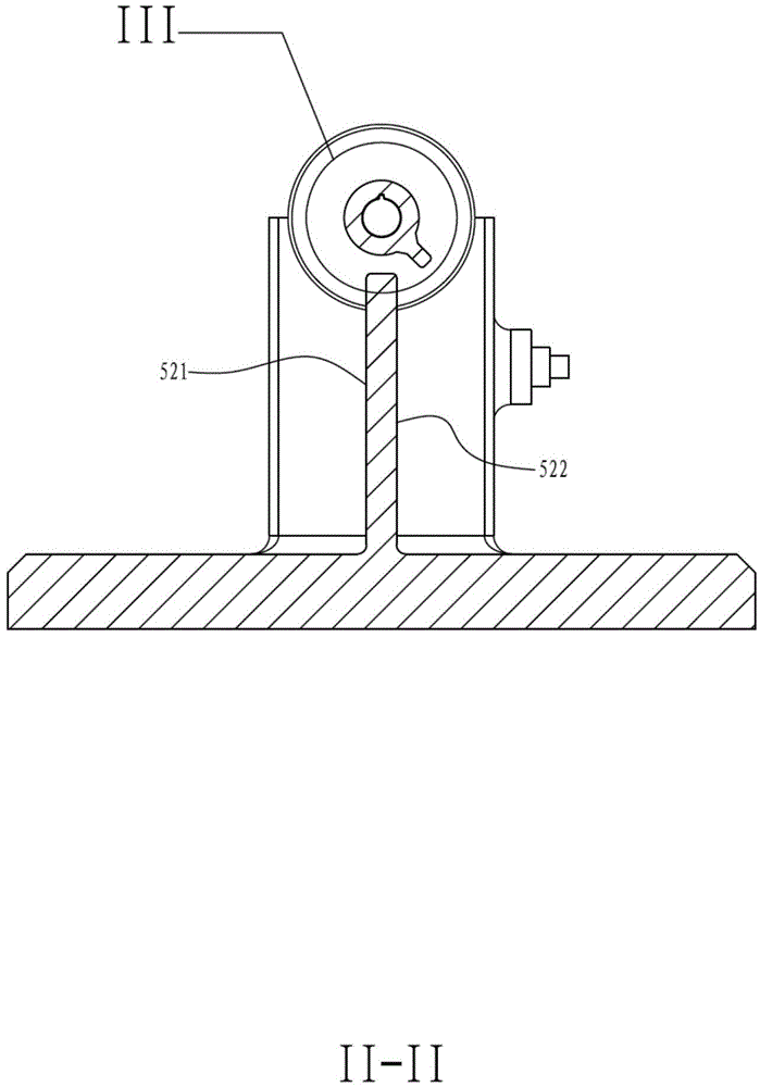
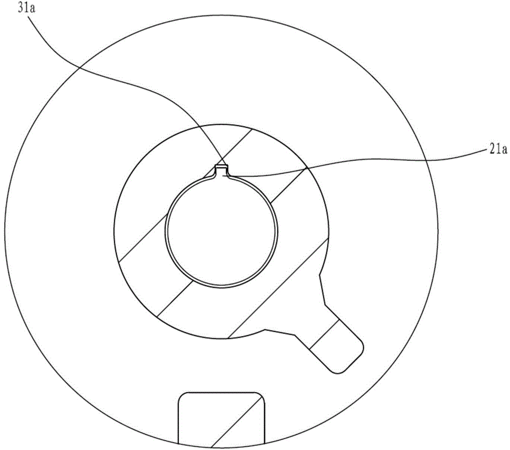
[0020] Please also refer to figure 1 , figure 2 and image 3 , a light bulb durability test device 100 provided in an embodiment of the present invention is used to test the durability of a light bulb (not shown), and the light bulb includes a threaded lamp cap (not shown) and a light emitting part (not shown) ). The light bulb durability testing device 100 includes a bottom plate 10 , a driving mechanism 20 , a clamping member 30 , a first elastic member 40 and a limiting mechanism 50 . The driving mechanism 20 drives the clamping part 30 to rotate, the clamping part 30 clamps the light bulb, and the first elastic part is compressed between the clamping part 30 and the driving mechanism 20, so that the clamping part 30 Clamp the bulb to reset. The limiting mechanism 50 ...


PUM


Abstract

The invention discloses a lamp bulb durability testing device comprising a bottom plate, a driving mechanism, a clamping member, a first elastic member, and a limiting mechanism. The driving mechanism comprises a rotating shaft and a machine body for driving the rotating shaft to rotate. The circumference of the rotating shaft is provided with a guide slider which is parallel to the axial direction. The clamping member comprises a sleeve and at least two second elastic members, the inner side of the sleeve is provided with a slide slot in which the guide slider is arranged in a sliding way, and the at least two second elastic members are used for clamping a light emitting part of a lamp bulb. The first elastic member is used for providing restoring force for the clamping member when the clamping member is away from the machine body. The bottom plate is provided with a threaded hole which is used for being in threaded connection with a threaded lamp holder of the lamp bulb. The clamping member clamps the light emitting part of the lamp bulb, and the rotating shaft drives the lamp bulb to rotate when rotating, so that the lamp holder of the lamp bulb is arranged in the threaded hole in a rotatable manner. The durability of the lamp bulb during use can be simulated, and the reliability of the lamp bulb can be conveniently tested.

Description

technical field [0001] The invention relates to the lighting field, in particular to a light bulb durability test device. Background technique [0002] Special lamps are widely used in various industries because of their high safety and reliability. The most important components in lamps are light sources and electrical components, and the devices that maintain the position of the light source and connect the light source with electrical components are lamps. When the lamp holder is connected to the light source, the method is a spiral, and the light source is fixed in the lamp holder by thread rotation. At the same time, the thread in the lamp holder has another function to provide power to the light source, and the thread in the lamp holder It is a metal part. The lamp holder of the light source is also a metal part. It plays the role of fixing the light source and transmitting electric energy. When the two metals are used in a long-term stress environment (such as: vibrat...

Claims


Application Information

Patent Timeline
IPC IPC(8): G01M11/00
Inventor 周明杰汪辉
Owner OCEANKING DONGGUAN LIGHTING TECH
Features
  • Generate Ideas
  • Intellectual Property
  • Life Sciences
  • Materials
  • Tech Scout
  • Unparalleled Data Quality
  • Higher Quality Content
  • 60% Fewer Hallucinations
Learn More