A chamber cleaning device and its control method

一种清洁装置、控制方法的技术,应用在腔室清洁装置及其控制领域,能够解决清洁效率低、环境因素改变等问题

Inactive Publication Date: 2017-03-08
HEFEI BOE OPTOELECTRONICS TECH +1
View PDF7 Cites 0 Cited by
  • Summary
  • Abstract
  • Description
  • Claims
  • Application Information

AI Technical Summary

Problems solved by technology

[0006] Embodiments of the present invention provide a chamber cleaning device and its control method, which can solve the problems of changing environmental factors and low cleaning efficiency in the chamber of an exposure machine in the cleaning technology

Method used


Image

  • A chamber cleaning device and its control method
  • A chamber cleaning device and its control method
  • A chamber cleaning device and its control method

Examples


Embodiment 1

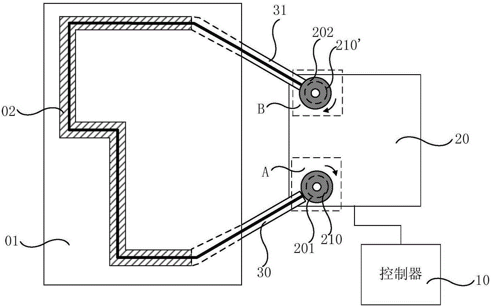
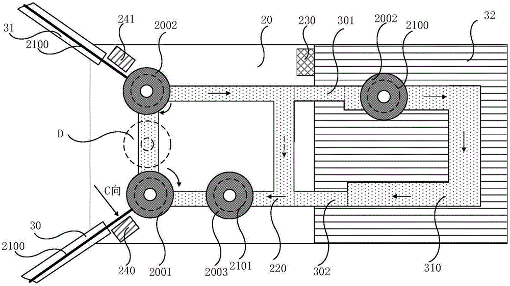
[0046] Such as figure 2 As shown, the supply device 20 may further include an annular supply guide rail 220 on which the first station A and the second station B are arranged. The reels ( 201 and 202 ) are installed on the supply guide rail 220 , and can move along the supply guide rail 220 under the control of the controller 10 . In this way, the supply guide rail 220 can provide a movement path for realizing the automatic replacement of the reel.

[0047] In order to realize automatic replacement of reels, the supply device 20 may further include a first replacement unit 240 and a second replacement unit 241 .

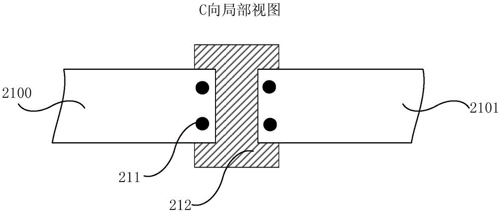
[0048] Specifically, the first replacement unit 240 can be arranged between the delivery inlet 30 and the first station A, and is used to connect the ends and the starting ends of two adjacent rolls of cleaning cloth 210;

[0049] The second replacement unit 241 is arranged between the delivery outlet 31 and the second station B, and is used to separate the end an...

Embodiment 2

[0070] Such as figure 2 As shown, the chamber cleaning device may further include a reduction device 32 to realize the reduction treatment of the cleaning cloth 210 .

[0071] Specifically, a restoring guide rail 310 may be provided in the restoring device 32 . The reduction guide rail 310 is connected to the supply guide rail 220 through a reduction inlet 301 and a reduction outlet 302 . In this way, the restoring device 32 can restore the cleaned cleaning cloth 210 so that it can be reused. The specific restoration process may be cleaning and drying the cleaning cloth 210 . Alternatively, when the cleaning cloth 210 is an activated carbon fiber cloth, the activated carbon fiber cloth may be reduced by a desorption method. The specific desorption methods may include: high temperature desorption, decompression desorption, flushing desorption, displacement desorption, magnetization desorption, ultrasonic desorption and so on.

[0072] In addition, the chamber cleaning device...

Embodiment 3

[0090] The cleaning track 02, as Figure 4 As shown, at least one position adjuster 40 may be included. The position regulators 40 may be distributed inside the chamber 01 along a preset track.

[0091] Wherein, the aforementioned preset track refers to the running track of the cleaning cloth 210 preset in the chamber. The design principle is that the cleaning cloth 210 cannot affect the normal operation of other devices in the chamber 01 while it is running along the preset track. For example, when the chamber 01 is a working chamber of an exposure machine, an object stage for carrying a substrate to be exposed, a light source for exposing, and a mask plate are arranged in the working chamber of the exposure machine. Therefore, the above-mentioned running track needs to bypass the exposure working parts and working areas such as the stage, the light source, and the mask plate, so as to avoid the impact of the cleaning cloth 210 on the substrate, The mask plate or the light...


PUM


Abstract

The invention relates to a chamber cleaning device and a control method thereof, which can solve the problem of low cleaning efficiency inside the chamber of an exposure machine. The chamber cleaning device includes: a controller for providing control signals, a supply device, and a cleaning track disposed inside the chamber. The supply equipment is provided with a first station and a second station, the first station corresponds to the conveying inlet, and the second station corresponds to the conveying outlet; the supply equipment includes at least two reels, and a cleaning machine partially located on the cleaning track. cloth, the reel located at the first station is connected to one end of the cleaning cloth, and is used to transport the cleaning cloth from the conveying inlet to the cleaning track, and the reel located at the second station is connected to the other end of the cleaning cloth. Collect the cleaning cloth that passes through the conveyor outlet.

Description

technical field [0001] The invention relates to the field of display technology, in particular to a chamber cleaning device and a control method thereof. Background technique [0002] TFT-LCD (Thin Film Transistor Liquid Crystal Display, Thin Film Transistor Liquid Crystal Display), as a flat panel display device, has become more and more popular due to its small size, low power consumption, no radiation and relatively low production cost. It is widely used in the field of high-performance display. [0003] TFT-LCD consists of an array substrate and a color filter substrate. The existing TFT-LCD manufacturing process mainly includes four stages, which are color filter preparation, Array (array substrate manufacturing) process, Cell (liquid crystal box preparation) process and Module (module assembly) process. As an important part of TFT-LCD production, the Array process usually forms independent TFT array circuits on a glass substrate, and each array circuit corresponds to...

Claims


Application Information

Patent Timeline
Patent Type & Authority Patents(China)
IPC IPC(8): B08B1/04B08B1/00B08B13/00
CPCB08B9/087B08B13/00B08B1/143
Inventor 胡瑾孟祥明节昌凯
Owner HEFEI BOE OPTOELECTRONICS TECH
Why Eureka
Try Eureka