Continuous track self-propelled type air-conveying high-range spraying machine

A self-propelled, high-range technology, which is applied in the fields of trapping or killing insects, applications, animal husbandry, etc., can solve the problems of limited working space, waste of resources, environmental pollution, etc., and achieve spray distance and range improvement, comprehensive Improved performance and better overall performance

Active Publication Date: 2015-06-24
SUZHOU AGRIBOT AUTOMATION TECH
View PDF9 Cites 9 Cited by
  • Summary
  • Abstract
  • Description
  • Claims
  • Application Information

AI Technical Summary

Problems solved by technology

These devices generally adopt a large-capacity "rinse type" operation method. The probability that the liquid medicine can accurately reach the lesion is small and uneven, and the liquid medicine is lost into the soil, causing environmental pollution and waste of resources, and at the same time poses a huge threat to human health.
Moreover, for some tall and luxuriant plants such as fruit trees and forest trees, traditional pesticide application methods cannot effectively control their diseases and insect pests.
In addition, in some specific environments, such as in mountainous or hilly areas, the terrain is undulating, the road conditions are bad, the working space is limited, the operation of large-scale pesticide application machinery is difficult, the manual work is intensive, and the traditional sprayer has a large volume and a high center of gravity. Difficult to apply in the aforementioned environment
In other words, the overall performance of traditional spray equipment is poor

Method used


Image

  • Continuous track self-propelled type air-conveying high-range spraying machine
  • Continuous track self-propelled type air-conveying high-range spraying machine
  • Continuous track self-propelled type air-conveying high-range spraying machine

Examples


Embodiment Construction

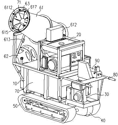
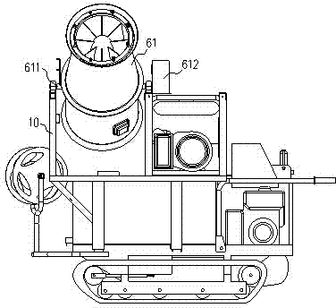
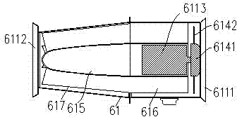
[0033] Examples, see figure 1 and figure 2 As shown, the crawler self-propelled wind-supplied high-range sprayer includes a vehicle frame 10 usually welded by steel materials. The vehicle frame 10 is provided with a generator set 20, an engine 30, a gearbox 40 connected to the engine 30, a crawler belt 50 connected to the gearbox 40 and positioned at the bottom of the frame 10, and a rotatable wind guide tube 61. , a medicine box 70 , a spray head 71 fixed on the opening of the air guide tube 61 , and the spray head 71 is connected to the medicine box 70 through a water pipe (not shown in the figure). Usually, the mouth of the air guide tube 61 is provided with a nozzle holder 63 , and the nozzle 71 is fixed on the nozzle holder 63 . Moreover, the vehicle frame 10 is also provided with a handrail 80 .

[0034] Further speaking, the medicine box 70 is located at the middle front side of the vehicle frame 10 , the engine 30 and the gearbox 40 are located at the middle re...


PUM


Abstract

The invention discloses a continuous track self-propelled type air-conveying high-range spraying machine. The continuous track self-propelled type air-conveying high-range spraying machine comprises a frame, wherein a generator set, an engine, a speed changing box, a continuous track, a rotatable air guiding barrel, a medicine box and a sprayer are arranged on the frame; the speed changing box is in power connection to the engine; the continuous track is in power connection to the speed changing box and is positioned on the lower portion of the frame; the sprayer is fixed on an opening portion of the air guiding barrel and is connected to the medicine box through a water tube; and armrests are also arranged on the frame. Locations of the various components are optimized reasonably, internal components of the air guiding barrel and a rotating mode of the air guiding barrel are optimized, so that the center of gravity of the spraying machine is greatly reduced, the size of the spraying machine is also reduced greatly, the air guiding barrel can spray out large air flow, a rotating angle is large, and a spraying distance and a spraying range are increased. Moreover, owing to the small size and the low center of gravity of the spraying machine, the spraying machine is easy to operate, and the comprehensive performance of the spraying machine is greatly improved.

Description

technical field [0001] The invention relates to the technical field of agricultural machinery, in particular to a crawler self-propelled air-driven high-range sprayer. Background technique [0002] As a large agricultural country, my country has a large demand for pesticide use and serious loss, causing serious pollution to the environment. At present, the spraying machines used in plant protection operations mainly include knapsack sprayers, motorized knapsack foggers, pedal sprayers, and motorized spray guns. These devices generally adopt a large-capacity "rinse type" operation method. The probability that the liquid medicine can accurately reach the lesion is small and uneven, and the liquid medicine is lost into the soil, causing environmental pollution and waste of resources, and at the same time poses a huge threat to human health. . Moreover, for some tall and luxuriant plants such as fruit trees and forest trees, traditional pesticide application methods cannot eff...

Claims


Application Information

Patent Timeline
Patent Type & Authority Applications(China)
IPC IPC(8): A01M7/00
Inventor 耿长兴王蓬勃王大帅李伟牛明强叶新华
Owner SUZHOU AGRIBOT AUTOMATION TECH
Why Eureka
Try Eureka