sheet metal cutting device

A technology for cutting devices and metal plates, which is applied in metal sawing equipment, sawing machine devices, metal processing equipment, etc., can solve problems such as time-consuming and cost-consuming, unsatisfactory shape of metal plates, poor shape and structure of final products, etc., to achieve Improved cut surface quality, cost and time savings

Active Publication Date: 2017-06-13
浦项股份有限公司 +1
View PDF5 Cites 2 Cited by
  • Summary
  • Abstract
  • Description
  • Claims
  • Application Information

AI Technical Summary

Problems solved by technology

[0004] However, when "cutting lumps" exist in the cut metal plate, it is determined that the shape of the metal plate is not ideal. Not only that, when the metal plate is later welded or obtained for special purposes such as ships, steel pipes or structures During processing, there is a hidden danger of poor shape and structure of the final product
In order to solve such a problem, it may be considered to perform a secondary processing process for removing the cut surface of the metal plate formed with "cutting lumps", but this not only consumes time and cost, but also has the disadvantage that even through such secondary processing It is also difficult to completely remove the problem of "cutting and agglomeration" in the process

Method used


Image

  • sheet metal cutting device
  • sheet metal cutting device
  • sheet metal cutting device

Examples


Embodiment Construction

[0039] The purpose, specific advantages and novel features of the present invention will become more apparent through the following description and examples in connection with the accompanying drawings. Note that, in this specification, when assigning reference numerals to constituent elements in the respective drawings, if the same constituent elements are shown in different drawings, the same numerals are assigned as much as possible. Moreover, in the process of describing the present invention, if it is considered that the specific description of related known technologies may cause unnecessary confusion to the gist of the present invention, the detailed description will be omitted.

[0040] Hereinafter, embodiments of the present invention will be described in detail with reference to the drawings.

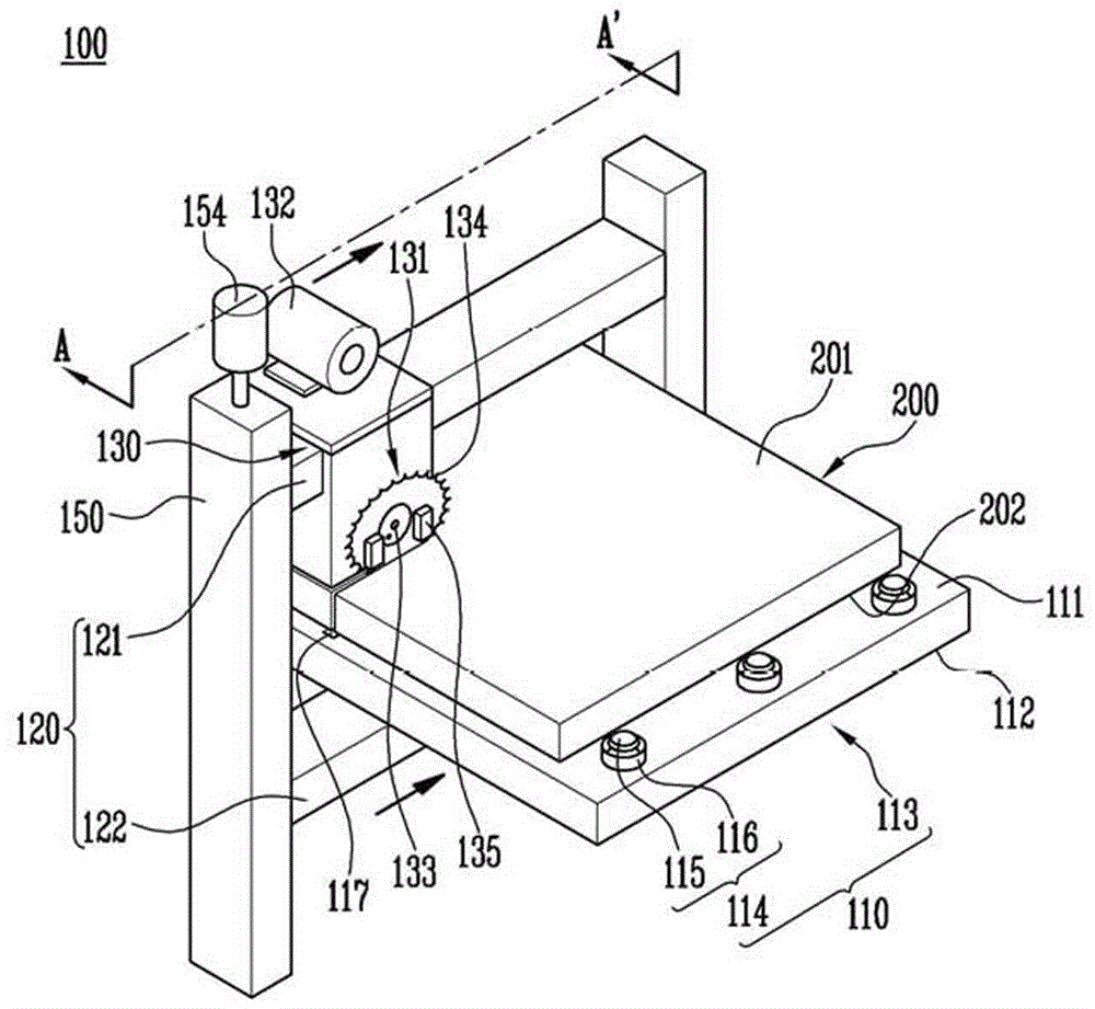
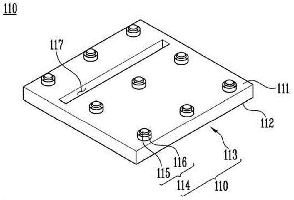
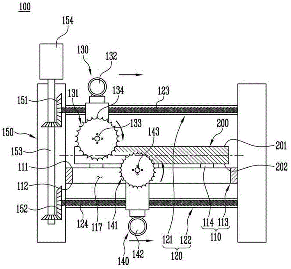
[0041] figure 1 It is a schematic perspective view of the sheet metal cutting device 100 according to the embodiment of the present invention. Hereinafter, the metal plate c...


PUM


Abstract

The present invention relates to a device for cutting a metal plate, comprising: a support part on which a metal plate is placed; first and second transfer frame parts positioned above and under the support part, respectively; a first cutting part which moves along the first transfer frame part and which includes a first saw blade part for cutting at least a part of the metal plate including the top of the metal plate by rotating; and a second cutting part which moves along the second transfer frame part and which includes a second saw blade part for cutting at least a part of the metal plate including the bottom of the metal plate by rotating. The present invention provides a device for cutting a metal plate, capable of cutting a metal plate without generating burrs on the cutting plane and without requiring secondary processing.

Description

technical field [0001] The invention relates to a sheet metal cutting device. Background technique [0002] Gas torches have traditionally been used when cutting sheet metal, especially thick sheets. At this time, in the case of cutting the metal plate with a gas torch, the metal plate heated by the gas torch will undergo an oxidation reaction with oxygen, and under the action of the heat of the oxidation reaction, a molten metal portion will be formed at the heated part, and by The molten metal part flows downward due to gravity, and a gap is formed between the metal plates, thereby cutting the metal plates. [0003] In this case, the molten metal flowing downward condenses on the lower portion of the cut surface and the lower surface and edge portion of the metal plate to form a site called “cut lump”. Such a phenomenon occurs not only in gas torch cutting, but also in plasma cutting, laser cutting, or Brown gas (Brown Gas) cutting, which is a cutting that utilizes a gap...

Claims


Application Information

Patent Timeline
Patent Type & Authority Patents(China)
IPC IPC(8): B23D45/10B23D47/02B23D47/08
CPCB23D45/027B23D45/10B23D47/04
Inventor 文昌晧申健崔刚赫郑基永李圣珍林承昊金英贤金秉辰金弘基
Owner 浦项股份有限公司
Why Eureka
Try Eureka